![]()
FINAL REPORT ON THE AUDIT OF THE MOSS LANDING POWER PLANT
![]()
CONDUCTED UNDER GENERAL ORDER 167
TO DETERMINE COMPLIANCE WITH
OPERATION, MAINTENANCE, AND LOGBOOK STANDARDS
ELECTRIC GENERATION PERFORMANCE BRANCH
CONSUMER PROTECTION AND SAFETY DIVISION
CALIFORNIA PUBLIC UTILITIES COMMISSION
505 VAN NESS AVENUE
 SAN FRANCISCO, CA 94102
October 31, 2007
Richard W. Clark, Director
Consumer Protection and Safety Division
Table of Contents
Section 1 - Safety Hazards Requiring Immediate Corrective Action 1414
Finding 1.1 - Slip, Trip and Fall Hazards and Potential Asbestos Contamination 1414
Section 2 - Violations Requiring Corrective Action 2222
Finding 2.1 - The plant lacks an adequate flow-assisted corrosion program 2222
Finding 2.2 - The plant lacks an inspection procedure for supports of high-energy piping 2424
Finding 2.3 - The plant has neither detected early signs of failure nor prevented repeated failures of turbine blades 3232
Finding 2.4 - The plant has no records showing that contractors or plant staff are certified and trained in hazardous waste and environmental emergency response 3333
Finding 2.5 - The plant lacks a written policy and procedure for boiler inspection 3636
Finding 2.6 - The plant is not up-to-date with emergency drills and response measures 3838
Finding 2.7 - The plant lacks a standardized system for storing, retrieving, and revising plant drawings 4141
Finding 2.8 - The job descriptions and table of contents of the plant's written procedures should be updated 4343
Finding 2.9 - The plant has not completely implemented its computerized inventory system as required by its own procedures 4545
Finding 2.10 - The plant does not test motor insulation resistance at intervals prescribed in the plant's predictive maintenance schedule 4747
Finding 2.11 - The plant has delayed installation of recording equipment for security cameras 4848
Observation 3.1 - Plant Security 4949
Observation 3.2 - Housekeeping 5151
Observation 3.3 - Plant Safety 5353
Observation 3.4 - Contractor Work Management 5555
Observation 3.5 - Training Support 5656
Observation 3.6 - Records of Operation 5757
Observation 3.7 - Balance of Plant Maintenance 5858
Observation 3.8 - Spare Parts and Materials 6060
Observation 3.9 - Online Procedures 6161
Observation 3.10 - Other Station Activities 6262
Observation 3.11 - Fire Protection 6363
Observation 3.12 - Equipment Performance Monitoring 6565
Observation 3.13 - Feedwater Chemistry 6868
Observation 3.14 - Regulatory Compliance 7070
Observation 3.15 - Condition of Maintenance Equipment 7171
List of Figures
Figure 1 -- Moss Landing Power Plant as seen from Highway 1. 1111
Figure 2 -- Units 1 and 2 are new, combined-cycle units. 1212
Figure 3 -- Units 6 and 7; conventional, once-through, supercritical boiler units. 1212
Figure 4 -- Disused equipment allowed to accumulate on Level 104 of Units 6 and 7. 1515
Figure 5 -- Disused piping and scaffolds accumulating on Level 104 of Units 6 and 7. 1515
Figure 6 -- Disused scaffolds accumulating on Level 88 of Units 6 and 7. 1616
Figure 7 -- Disused scaffolds accumulating on Level 88 of Units 6 and 7. 1616
Figure 8 -- Insulation, possibly containing asbestos, on Level 104 of Units 6 and 7. 1717
Figure 9 -- Standing water caused by a clogged drain on Level 88 of Units 6 and 7. 1717
Figure 10 -- Frangible insulation falling off an exposed pipe in the basement of Units 6 and 7. The pipes lack blue banding, which would indicate the absence of asbestos. Therefore, asbestos is assumed to be present. 1818
Figure 11 -- Insulation from the over head pipe; no asbestos containment precautions are evident. 1818
Figure 12 -- Scaffolding carts could be seen in many areas. These carts are surrounded with caution tape when the scaffolding is not in use. The yellow caution tape can be seen in this photo. 1919
Figure 13 -- The plant was unable to unclog the plugged drain. Rather, the plant applied epoxy cement over it to correct the low spot and allow proper drainage. Also see Figure 9. 2020
Figure 14 -- To prevent water accumulation, the plant used epoxy cement to re-grade the area for proper drainage. 2020
Figure 15 -- To prevent water accumulation, the plant used epoxy cement to re-grade the area for proper drainage. 2121
Figure 16 -- Plant staff used blue banding and dimpled aluminum wrapping to indicate non-asbestos pipe insulation. 2121
Figure 17 -- Severely deteriorated pipe hanger spring cans as seen from turbine deck of Units 6 and 7. 2525
Figure 18 -- Severely rusted pipe hanger spring cans visible from turbine deck of Units 6 and 7. 2525
Figure 19 -- Severely rusted pipe hanger rods visible from Level 102 of Units 6 and 7. 2626
Figure 20 -- Severely deteriorated pipe hanger rods visible from Level 102 of Units 6 and 7. 2626
Figure 21 -- The plant installed new galvanized spring cans to replace deteriorated supports. 2727
Figure 22 -- Close-up view of a new spring support. 2828
Figure 23 -- This is a close-up view of a simple spring support with the load indicator in the center of the polygon. This indicates that the support is loaded evenly. 2828
Figure 24 -- This is a photo of a new twin simple spring support. Note the load indicator. 2929
Figure 25 -- An older spring support that has been painted to prevent further corrosion. 2929
Figure 26 -- This is a photo of a new hanger and pipe support on an older pipe. 3030
Figure 27 -- This is a photo of old rusted pipe support rods that have yet to be serviced or replaced. 3030
Figure 28 -- One of three emergency staging points or assembly areas. The information on the muster card, as seen here in a transparent enclosure, is to be updated semi-annually. 3939
Figure 29 -- This is a photo of the new siren installed on Level 88 of Units 6 & 7. 4040
Figure 30 -- Guard station at the main gate along Dolan Road. 5050
Figure 31 -- One of the three warehouses onsite; stocks are organized and labeled with bin location. 6060
Figure 32 -- The main machine shop. 7171
Figure 33 -- The secondary machine shop houses miscellaneous tools. 7272
The Consumer Protection and Safety Division (CPSD) presents this Final Report on the audit of Moss Landing Power Plant ("Moss Landing" or "the plant"). CPSD audited the plant for compliance with the California Public Utilities Commission's ("CPUC's" or "Commission's") General Order 167, which includes Operation, Maintenance, and Logbook Standards for power plants.
In September 2005, CPSD contacted Moss Landing to schedule the audit. Auditors subsequently spent a week at the plant site. While onsite, Auditors inspected equipment, examined documents, and interviewed plant personnel. CPSD issued its Preliminary Audit Report ("Preliminary Report") on October 23, 2006, and requested the plant to submit a response by November 23, 2006. Moss Landing requested and was granted an extension of this deadline. The plant submitted its response on December 8, 2006. CPSD and Moss Landing held a teleconference on February 16, 2007 to discuss the plant's response. On April 19, 2007, CPSD and Moss Landing met and conferred. The plant provided additional information and CPSD now issues this Final Audit Report.
In the Preliminary Report, CPSD identified twelve potential violations of various standards. Although the plant disputes many of CPSD's findings and their characterization as violations, the plant agreed to take various corrective actions, which are summarized below and further discussed in the report in sections entitled "Final Outcome and Follow-up."
Finding 1.1 In Units 6 and 7, Auditors found tripping hazards, standing water due to a clogged drain, deteriorating insulation and failure to follow asbestos mitigation procedures. In response, Moss Landing removed and stored all abandoned equipment that may cause trip and fall hazards. To prevent standing water, the plant applied epoxy cement to correct low spots and allow proper drainage. The plant repaired deteriorating insulation, identified asbestos-insulated equipment and initiated a regular inspection program. The plant also installed blue banding on non-asbestos insulation.
Finding 2.1 Moss Landing lacked a program to monitor and identify flow-assisted corrosion (FAC) in high-energy piping. Excessive corrosion in pipe walls can lead to catastrophic rupture of high pressure, high temperature steam piping, in turn resulting in injury and fatality. In response, Moss Landing created a high-energy piping inspection program. The program includes scheduled inspections to identify, assess, and implement repairs of creep, fatigue and flow-accelerated erosion/corrosion damage in high-energy piping and components.
Finding 2.2 Moss Landing lacked an inspection procedure for the supports of high-energy piping (HEP). Misadjusted or broken pipe supports can increase pipe stresses which, in the presence of corroded pipe walls, can also lead to catastrophic rupture. In response, the plant submitted a HEP inspection procedure covering hangers and supports for Units 1 and 2. CPSD requests that the plant submit a similar procedure for Units 6 and 7. Finally, the plant should notify CPSD when it completes all repairs so that CPSD can perform a follow-up inspection.
Finding 2.3 Moss Landing had neither detected early signs of failure nor prevented repeated failures of prototype turbine blades in Units 1 and 2. In response, the plant explained that the failure was instantaneous and that there was no sign on their monitoring instruments indicating precursory problems. To prevent recurrence, the plant now inspects compressor blades every 8,000 operating hours as opposed to GE's recommended frequency of 12,000 hours. The plant is replacing compressor blades with blades of the original design on all gas turbines.
Finding 2.4 The plant had no records showing that contractors or plant staff were certified or trained in hazardous waste and environmental emergency response. Nor did the plant make available to its staff a list of qualified emergency response contractors. In response, the plant now uses a "Contractor Qualification Form" to verify that contractors have appropriate training, certificates, bonds and insurance prior to being awarded a contract. The plant also implemented new safety and quality control procedures for employees and contractors. As a result of the Audit, the plant discovered and repaired a faulty computer link in the Electronic Database System. The plant now keeps all training records and contractor information in the database. Finally, the plant relies on hazardous material handlers for all associated emergencies. The plant now makes the list of qualified handlers available to all plant personnel.
Finding 2.5 The plant lacked a written policy and procedure for boiler inspections for Units 6 and 7. In response, the plant has written a procedure to document its boiler inspection and maintenance program which includes an annual inspection program, historical repair records, acceptance criteria, and prioritizing of maintenance work.
Finding 2.6 The plant had not held annual emergency drills, installed an effective alarm system, installed an effective system accounting for all people onsite during emergencies, nor consistently designated emergency assembly areas. In response, the plant conducted a full scale evacuation drill, improved its evacuation procedure and installed a new audible warning system. It also updated all rosters (muster cards) and will continue to update them on a quarterly basis. However, sirens cannot be heard in some plant areas. Also, the plant needs to show that it has updated all evacuation maps to include both primary and alternate assembly areas. CPSD requests that the plant correct these deficiencies.
Finding 2.7 The plant did not have a standardized system for storing, retrieving, and revising plant drawings. In response, the plant revised its document control procedure to track document revisions and to require an out card to check out documents from its library. The plant has trained its entire technical team on how to access library documents. The plant also added two full-time positions to implement this new document control policy.
Finding 2.8 The job descriptions and table of contents of the plant's written procedures were outdated. In response, the plant updated its procedures and corrected the identified discrepancies.
Finding 2.9 The plant had not completely implemented its computerized inventory system as required by its own procedures. In response, the plant generated an inventory report and demonstrated that Maximo is fully functional. The plant also designated a Maintenance Manager who now has full access to control the plant's inventory.
Finding 2.10 The plant did not test motors at intervals prescribed in the plant's predictive maintenance schedule. In response, the plant installed a system that continuously meggers motors, eliminating the need for weekly manual meggering. CPSD requests that the plant submit the revised work order that shows the new schedule.
Finding 2.11 The plant had delayed installation of recording equipment for security cameras. In response, the plant installed a DVD recording system on all security camera feeds. The system retains images up to 30 days.
CPSD is satisfied that the above corrective actions will adequately address the issues raised in the Preliminary Report. CPSD requests that the plant resolve and report on outstanding issues by June 30, 2008.
On September 27, 2005, CPSD notified Moss Landing of the audit, and requested pertinent documents and data. CPSD's audit team included Jim Cheng, Ron Lok, Chris Lee, Chuck Magee, and Rick Tse. The Auditors reviewed the materials and subsequently visited the plant from December 5, 2005 through December 9, 2005. While onsite, Auditors inspected equipment, examined documents, observed plant operations, and interviewed plant personnel.
On October 23, 2006, CPSD issued its Preliminary Audit Report ("Preliminary Report") and asked the plant to respond by November 23, 2006 with a Corrective Action Plan. The plant requested and was granted an extension of this deadline. On December 8, 2006, the plant submitted its response. CPSD and Moss Landing held a teleconference on February 16, 2007 to discuss the plant's response. On April 19, 2007, CPSD and Moss Landing met and conferred. The plant provided additional information and CPSD now issues this Final Audit Report.
CPSD conducted the audit with two approaches. First, Auditors focused on past incidents to evaluate whether the plant needed improvements in operations and maintenance policies. Auditors also examined whether the plant's programs and procedures met various Operation, Maintenance, and Logbook Standards. The team targeted the following standards in the audit:
A. Safety and training
B. Balance of maintenance, procedures and documentation, and work management
C. Spare parts and procurement management
D. Equipment performance and engineering support
E. Chemistry control
F. Other regulatory requirements
G. Equipment history
H. Maintenance facilities and equipment conditions
I. Routine inspections and records of operation
J. Performance testing and emergency grid operations
K. Plant security and readiness
L. Logbook standards and compliance document
CPSD identified twelve potential violations of various standards. Auditors found one violation that presented an imminent safety hazard as stated in Section 1 of this report. Section 2 of the report describes the remaining eleven potential violations as well as the plant's response to them. Section 3 describes other audit activities where Auditors found no violation of standards.
Although the plant disputes many of CPSD's findings and their characterization as violations, the plant agreed to take various corrective actions, which are summarized below and further discussed in the report in sections entitled "Final Outcome and Follow-up."
Finding 1.1 In Units 6 and 7, Auditors found tripping hazards, standing water due to a clogged drain, deteriorating insulation and failure to follow asbestos mitigation procedures. In response, Moss Landing removed and stored all abandoned equipment that may cause trip and fall hazards. To prevent standing water, the plant applied epoxy cement to correct low spots and allow proper drainage. The plant repaired deteriorating insulation, identified asbestos-insulated equipment and initiated a regular inspection program. The plant also installed blue banding on non-asbestos insulation.
Finding 2.1 Moss Landing lacked a program to monitor and identify flow-assisted corrosion (FAC) in high-energy piping. Excessive corrosion in pipe walls can lead to catastrophic rupture of high pressure, high temperature steam piping, in turn resulting in injury and fatality. In response, Moss Landing created a high-energy piping inspection program. The program includes scheduled inspections to identify, assess, and implement repairs of creep, fatigue and flow-accelerated erosion/corrosion damage in high-energy piping and components.
Finding 2.2 Moss Landing lacked an inspection procedure for the supports of high-energy piping (HEP). Misadjusted or broken pipe supports can increase pipe stresses which, in the presence of corroded pipe walls, can also lead to catastrophic rupture. In response, the plant submitted a HEP inspection procedure covering hangers and supports for Units 1 and 2. CPSD requests that the plant submit a similar procedure for Units 6 and 7. Finally, the plant should notify CPSD when it completes all repairs so that CPSD can perform a follow-up inspection.
Finding 2.3 Moss Landing had neither detected early signs of failure nor prevented repeated failures of prototype turbine blades in Units 1 and 2. In response, the plant explained that the failure was instantaneous and that there was no sign on their monitoring instruments indicating precursory problems. To prevent recurrence, the plant now inspects compressor blades every 8,000 operating hours as opposed to GE's recommended frequency of 12,000 hours. The plant is replacing compressor blades with blades of the original design on all gas turbines.
Finding 2.4 The plant had no records showing that contractors or plant staff were certified or trained in hazardous waste and environmental emergency response. Nor did the plant make available to its staff a list of qualified emergency response contractors. In response, the plant now uses a "Contractor Qualification Form" to verify that contractors have appropriate training, certificates, bonds and insurance prior to being awarded a contract. The plant also implemented new safety and quality control procedures for employees and contractors. As a result of the Audit, the plant discovered and repaired a faulty computer link in the Electronic Database System. The plant now keeps all training records and contractor information in the database. Finally, the plant relies on hazardous material handlers for all associated emergencies. The plant now makes the list of qualified handlers available to all plant personnel.
Finding 2.5 The plant lacked a written policy and procedure for boiler inspections for Units 6 and 7. In response, the plant has written a procedure to document its boiler inspection and maintenance program which includes an annual inspection program, historical repair records, acceptance criteria, and prioritizing of maintenance work.
Finding 2.6 The plant had not held annual emergency drills, installed an effective alarm system, installed an effective system accounting for all people onsite during emergencies, nor consistently designated emergency assembly areas. In response, the plant conducted a full scale evacuation drill, improved its evacuation procedure and installed a new audible warning system. It also updated all rosters (muster cards) and will continue to update them on a quarterly basis. However, sirens cannot be heard in some plant areas. Also, the plant needs to show that it has updated all evacuation maps to include both primary and alternate assembly areas. CPSD requests that the plant correct these deficiencies.
Finding 2.7 The plant did not have a standardized system for storing, retrieving, and revising plant drawings. In response, the plant revised its document control procedure to track document revisions and to require an out card to check out documents from its library. The plant has trained its entire technical team on how to access library documents. The plant also added two full-time positions to implement this new document control policy.
Finding 2.8 The job descriptions and table of contents of the plant's written procedures were outdated. In response, the plant updated its procedures and corrected the identified discrepancies.
Finding 2.9 The plant had not completely implemented its computerized inventory system as required by its own procedures. In response, the plant generated an inventory report and demonstrated that Maximo is fully functional. The plant also designated a Maintenance Manager who now has full access to control the plant's inventory.
Finding 2.10 The plant did not test motors at intervals prescribed in the plant's predictive maintenance schedule. In response, the plant installed a system that continuously meggers motors, eliminating the need for weekly manual meggering. CPSD requests that the plant submit the revised work order that shows the new schedule.
Finding 2.11 The plant had delayed installation of recording equipment for security cameras. In response, the plant installed a DVD recording system on all security camera feeds. The system retains images up to 30 days.
CPSD is satisfied that the above corrective actions will adequately address the issues raised in the Preliminary Report. CPSD requests that the plant resolve and report on outstanding issues by June 30, 2008.
Moss Landing is California's largest power plant site in terms of Megawatts (MW) capacity. It is located on Dolan Road in Moss Landing, an unincorporated town 20 miles north of Monterey, along Highway 1 in Monterey County (Figure 1).
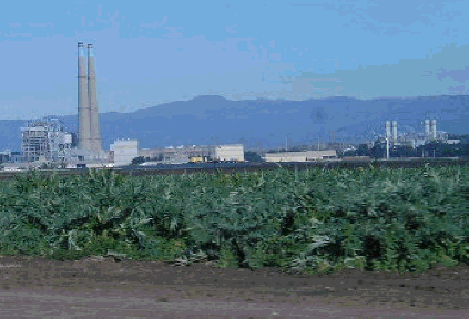
Figure 1 -- Moss Landing Power Plant as seen from Highway 1.
The 2,530 MW plant consists of four units. Units 1 and 2, 510 MW each, are new combined-cycle units. They began commercial operation in July 2002 (Figure 2).
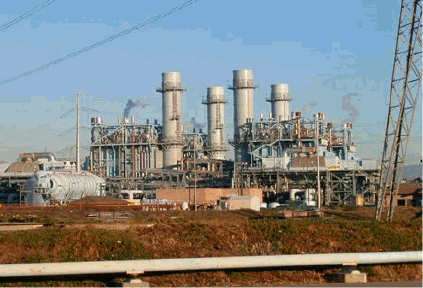
Figure 2 -- Units 1 and 2 are new, combined-cycle units.
Units 6 and 7, 755 MW each, use supercritical boilers, and opened in the late 1960s (Figure 3).
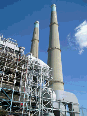
Figure 3 -- Units 6 and 7; conventional, once-through, supercritical boiler units.
Pacific Gas and Electric (PG&E) built and ran Moss Landing. In July 1998, when California restructured the electric market, PG&E sold the units to Duke Energy North America. Duke overhauled and modernized Units 6 and 7 and added new Units 1 and 2. Duke also demolished five decommissioned units. LS Power Equity Partners acquired Moss Landing from Duke in May of 2006. In April 2007, LS Power merged with Dynegy and Dynegy took ownership of the plant.
CPSD conducted a performance study on Moss Landing.1 First, CPSD compared Units 1 and 2 against other natural gas combined-cycle units for the period 2003 to 2006. Data show that the two units performed well compared to similar units across all indices. However in late 2004, the units experienced a performance setback when newly designed compressor blades suffered premature fatigue and broke off, damaging the compressor and turbine section. See Finding 2.3. Despite this isolated event, both units remained available to generate power over 90% of the time from 2003 to 2006. They also had an average 99% success rate on startups. The units underwent more scheduled outages over the years and their forced outage factor averaged less than 3%. Overall, the units' performance profile appeared exceptional.
Units 6 and 7 operated fewer hours and performed worse than other North American super-critical units for the period 1998 to 2006. Although MLPP overhauled the units in 2001 and 2002, equipment problems still occurred and weakened their performance. The units' EFORd averaged about 10% while similar units came in at about 8%. This figure has remained fairly constant from 1998, when California restructured the electric industry, through 2006. It should be noted that before deregulation in 1998, the units' average EFORd was actually higher than 10% during a time when the units were baseloaded, for which they were designed. This tends to dispel the notion, at least at these plants, that plants designed for baseload operation performed more reliably before deregulation.
Units 6 and 7 also had a lower success rate on startups than similar North American units. While similar units started up 97% of the time on average, Units 6 and 7 started up just 85% and 88% of the time, respectively, from 1998 to 2006. CPSD did not identify a specific cause for the lower rate, however possible causes include poor design, inadequate maintenance and/or operator training and possibly others.
In January 2007, MLPP secured a long term contract, under which the plant sells Unit 6 and 7's capacity to PG&E. This presumably will add incentives for MLPP to improve the units' performance.
SECTION 1 - SAFETY HAZARDS REQUIRING IMMEDIATE CORRECTIVE ACTION
Maintenance Standard 1 - Safety
The protection of life and limb for the work force is paramount. The company behavior ensures that individuals at all levels of the organization consider safety as the overriding priority. This is manifested in decisions and actions based on this priority. The work environment, and the policies and procedures foster such a safety culture, and the attitudes and behaviors of individuals are consistent with the policies and procedures.
Assessment Guidelines
A.2 Individuals at all levels in the organization contribute to the safety culture of the work environment through demonstrating a questioning attitude by challenging existing conditions, considering the potential adverse consequences prior to proceeding, and willingness to stop work in the face of uncertainty.
A.3 Individuals at all levels in the organization contribute to the safety culture of the work environment through demonstrating a willingness to identify problems and ensure they are corrected.
Operation Standard 1 - Safety
The protection of life and limb for the work force is paramount. GAOs have a comprehensive safety program in place at each site. The company behavior ensures that personnel at all levels of the organization consider safety as the overriding priority. This is manifested in decisions and actions based on this priority. The work environment and the policies and procedures foster such a safety culture, and the attitudes and behaviors of personnel are consistent with the policies and procedures.
FINDING 1.1 - SLIP, TRIP AND FALL HAZARDS AND POTENTIAL ASBESTOS CONTAMINATION
Auditors found tripping hazards, standing water (and potential damage to concrete) due to a clogged drain, and possible asbestos contamination, all potential violations of Operation and Maintenance Standards.
Trip and fall hazards exist on Levels 88 and 104 of Units 6 and 7, a potential violation of safety standards. In particular, the CPUC Auditor saw old equipment, pipes, excess scaffolding and used insulation lying next to guardrails and piled next to walkways (Figures 4 to 8).
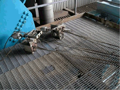
Figure 4 -- Disused equipment allowed to accumulate on Level 104 of Units 6 and 7.
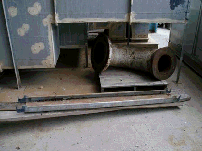
Figure 5 -- Disused piping and scaffolds accumulating on Level 104 of Units 6 and 7.
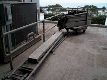
Figure 6 -- Disused scaffolds accumulating on Level 88 of Units 6 and 7.
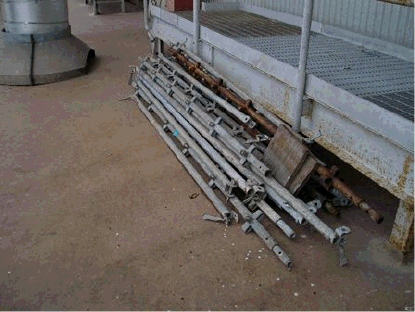
Figure 7 -- Disused scaffolds accumulating on Level 88 of Units 6 and 7.
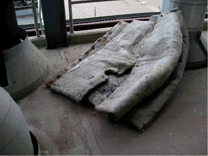
Figure 8 -- Insulation, possibly containing asbestos, on Level 104 of Units 6 and 7.
Standing water exists on Level 88 of Units 6 and 7, caused by a clogged drain (Figure 9), a potential violation of safety standards. In addition to creating slip and fall hazards, such water accumulation can lead to more significant structural damage. Standing water can seep into concrete and oxidize reinforcing bars (rebar). Resulting corrosion in rebar causes concrete to spall and flake.
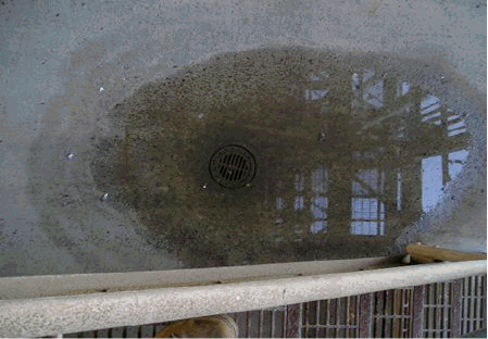
Figure 9 -- Standing water caused by a clogged drain on Level 88 of Units 6 and 7.
The CPSD Auditor observed insulation falling off of a pipe above the southeast cooling water intake manifold in the basement of Units 6 and 7 (Figures 10 and 11). The insulation lacked blue banding. The plant should treat all insulation without blue banding as asbestos-laden. The plant should have cordoned off the area and initiated asbestos containment and mitigation procedures.
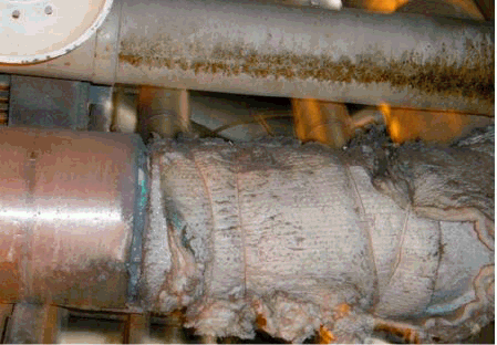
Figure 10 -- Frangible insulation falling off an exposed pipe in the basement of Units 6 and 7. The pipes lack blue banding, which would indicate the absence of asbestos. Therefore, asbestos is assumed to be present.
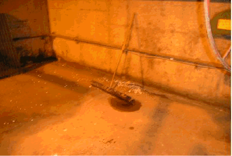
Figure 11 -- Insulation from the over head pipe; no asbestos containment precautions are evident.
To the contrary, plant staff routinely walked through the debris, and seemed unaware of the potential hazard. Plant staff would not commit to a date for testing or cleanup. This debris remained on the floor during the five-day audit visit.
The Audit Team discussed these (and other) findings with the Plant Manager at the conclusion of the site visit in December, 2005. The presence of these unsafe conditions indicates a lack of a cohesive safety culture or program or unsafe individual behaviors by plant personnel. The plant should correct these potential violations immediately.
Final Outcome and Follow-up
The plant corrected the safety hazards in this finding. The plant removed and stored away all abandoned equipment that may cause trip and fall hazards. To prevent standing water, the plant applied epoxy cement to correct low spots and allow proper drainage. In response to deteriorating insulation, the plant identified asbestos-insulated equipment, initiated a regular inspection program and asbestos containment and mitigation (ACM) training for all operations and maintenance personnel. The plant also installed blue banding on non-asbestos insulation.
The Auditor visited Levels 88 and 104 and confirmed that the plant had removed and properly stored excess equipment (Figure 12).
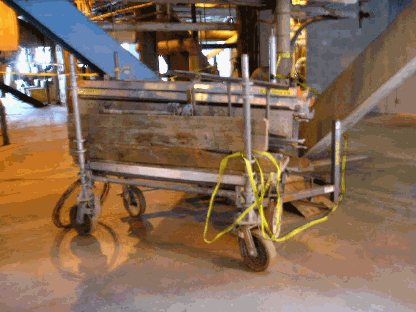
Figure 12 -- Scaffolding carts could be seen in many areas. These carts are surrounded with caution tape when the scaffolding is not in use. The yellow caution tape can be seen in this photo.
In areas where standing water can accumulate, plant staff applied epoxy cement to correct low spots and allow proper drainage. The plant was unable to unclog the plugged drain identified in the Preliminary Report. Rather, the plant applied epoxy cement to re-grade that area. Plant staff provided work orders and closed-out purchase orders which confirmed such work. The Auditor also visited the areas and confirmed that plant staff had completed the work (Figures 13 to 15).
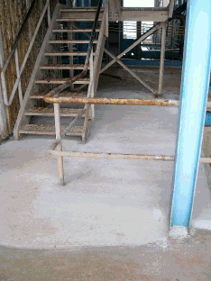
Figure 13 -- The plant was unable to unclog the plugged drain. Rather, the plant applied epoxy cement over it to correct the low spot and allow proper drainage. Also see Figure 9.
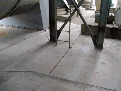
Figure 14 -- To prevent water accumulation, the plant used epoxy cement to re-grade the area for proper drainage.
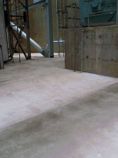
Figure 15 -- To prevent water accumulation, the plant used epoxy cement to re-grade the area for proper drainage.
Plant staff showed the Auditor changes to Job Plan 632 (item 110 pages 6 and 7), which require staff to install blue banding on all non-asbestos insulation. The Auditor toured the facility and confirmed that plant staff had used blue banding on non-asbestos pipe insulation (Figure 16). The plant also retrained its personnel on Asbestos Containment and Mitigation (ACM) procedures.
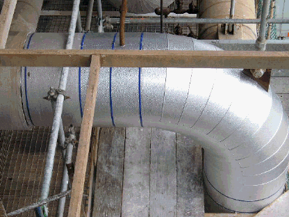
Figure 16 -- Plant staff used blue banding and dimpled aluminum wrapping to indicate non-asbestos pipe insulation.
This section describes eleven potential violations discovered during the audit that required corrective action. It also includes the plant's response to these findings. Moss Landing has corrected or has committed to correct all problems identified by the audit.
Operation Standard 27 - Flow-assisted Corrosion
Where circumstances require it, the GAO has a flow-assisted corrosion program, which identifies vulnerable equipment, provides for regular testing of that equipment, and responds appropriately to prevent high energy pipe failures.
Assessment Guidelines
The flow-assisted corrosion program takes into consideration factors such as:
A. Identification of the most susceptible piping components/areas and establishment of a sampling protocol consistent with engineering principles and practices.
B. Appropriate nondestructive testing (usually ultrasound) to determine the extent of pipe thinning (if any).
C. Where thinning is identified, establishment of a preventative maintenance program and replacement of piping in accordance with ASME recommendations.
D. Refer to the U.S. Dept. of Labor, Occupational Safety and Health Administration, Hazard Information Bulletin dated 10/31/96 for more information.
FINDING 2.1 - THE PLANT LACKS AN ADEQUATE FLOW-ASSISTED CORROSION PROGRAM
Moss Landing lacks a program to detect and correct flow-assisted corrosion (FAC) in high-energy piping, a potential violation of Operation Standards. The Auditor reviewed the plant's boiler and pipe inspection reports and found no such program.
Catastrophic ruptures of high-energy steam piping due to corrosion, while rare, are dangerous, destructive, and deadly to workers in the vicinity. Plants therefore should identify high-energy piping, test the piping regularly, and repair or replace corroded piping as recommended by ASME.2
In response to the Auditor's request for documentation of a FAC program for Units 6 and 7, the plant submitted an incomplete and outdated report performed by the plant's original owner, PG&E. Entitled "HEP-ML-96", the report analyzed the effects of erosion and corrosion on feedwater piping. However, the report did not cover other high-energy piping in the units. Furthermore, the report, dated October 22, 1996, was written more than ten years ago. Substantial corrosion may have occurred since then.
The plant should also develop a FAC monitoring program for Units 1 and 2. Although Units 1 and 2 are relatively new, the plant should already have determined when FAC testing should begin. Even though the plant inspects Units 1 and 2's steam generators annually, those inspections do not qualify as FAC monitoring programs, as reports from those inspections make clear. The reports recommended that the plant develop a FAC monitoring program.
FAC testing is overdue on Units 1, 2, 6 and 7. The plant must develop a FAC program to identify and monitor all high-energy piping.
Final Outcome and Follow-up
In response to our finding, the plant created a high-energy piping (HEP) program, dated November 6, 2006. The program includes scheduled inspections to identify, assess, and implement repairs of creep, fatigue and flow-accelerated erosion/corrosion damage in high-energy piping and components. Using methods specified by the program, the plant tracks the actual pipe wall thicknesses against those allowed by ASME B31.1, so that engineers can project when piping/fitting replacements or repairs will be necessary. During the meet and confer meeting, the Auditor discussed the results of the piping inspections with the engineer managing the program. The data, record keeping and inspection results should allow the plant to track and trend pipe wall thicknesses. As a result of recent inspections, the plant made several repairs to Units 6 and 7 and additional inspections are proceeding.
Maintenance Standard 7 - Balance of Maintenance Approach
The maintenance program includes the proper balance of the various approaches to maintenance, e.g., preventive, predictive, or corrective. The approach is adequately documented with consideration of economics and reliability of equipment or components, and their affect on reliable operation of the unit. Operating experience is factored into the program. Maintenance procedures and documents should include the generation equipment and all those components owned by the generation owner directly connected to the plant that are an integral part of delivering power to the grid including fuel supply systems, electrical switchyards, transmissions lines, penstocks, flumes, exhaust system, etc.
Assessment Guidelines
A. Preventive maintenance is proper for the equipment whose failure adversely impacts safety or reliable operation or results in forced outages, or significant derates.
B. Preventive maintenance is appropriately balanced between time based and condition based, as appropriate for the equipment.
L. Equipment or components that are degraded or not performing their intended function are restored in a timely manner, consistent with their respective importance to personnel safety and efficient, reliable operation of the unit.
FINDING 2.2 - THE PLANT LACKS AN INSPECTION PROCEDURE FOR SUPPORTS OF HIGH-ENERGY PIPING
In Units 6 and 7, the plant has deferred maintenance on supports for high-energy piping, and lacks an inspection procedure for those supports, potentially violating Maintenance Standards.
Misadjusted or broken supports increase pipe stress. In the presence of reduced pipe wall thickness due to corrosion, such stress can lead to catastrophic failure. In particular, the Auditor noticed that spring cans in Units 6 and 7 had nearly rusted away (Figures 17 and 18). While the exterior spring cans bear no load, they protect the springs they enclose.

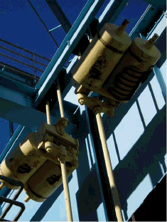
Figure 17 -- Severely deteriorated pipe hanger spring cans as seen from turbine deck of Units 6 and 7.

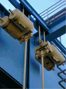
Figure 18 -- Severely rusted pipe hanger spring cans visible from turbine deck of Units 6 and 7.
The Auditor also observed evidence of rust and deterioration on piping hanger rods throughout Units 6 and 7 (Figures 19 and 20).
![]()
![]()

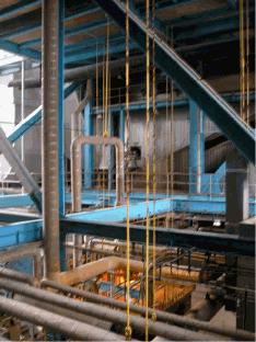
Figure 19 -- Severely rusted pipe hanger rods visible from Level 102 of Units 6 and 7.
![]()
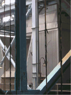
Figure 20 -- Severely deteriorated pipe hanger rods visible from Level 102 of Units 6 and 7.
In response to this finding, the plant inspected the pipe supports on the high-energy piping (HEP) systems of Units 6 and 7. They found two broken and several misadjusted spring cans. The plant also scheduled a Hot Pipe Inspection in a Work Order (#64732), for February 2006. Hot Pipe Inspections confirm that piping behaves as predicted and that pipe supports carry the design loads. Auditors have not confirmed whether the latter inspection has taken place.
The plant should establish and implement procedures for regular pipe inspections in both cold and hot conditions and correct any misadjusted, worn or broken supports and/or components.
Final Outcome and Follow-up
In response to our finding, the plant has agreed to develop inspection procedures and make needed repairs. The plant has already created Procedure No. 1-017 entitled "Unit 1 & 2 HEP Hanger Inspection". It requires the plant to inspect HEP hangers and supports on Units 1 and 2 only. The procedure did not include Units 6 and 7, which is the subject of this finding.
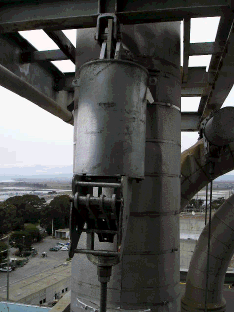
The Auditor inspected the facility and found that plant staff had repaired most spring cans on high-energy piping but had not repaired rod supports for other piping (Figures 21 to 27). Under Work Order #64732, plant staff also inspected Units 6 and 7's hangers while the plant was in operation and the pipe supports were hot.
CPSD requests that the plant submit an HEP hanger inspection procedure for Units 6 and 7 and make all necessary repairs by June 30, 2008.
![]()

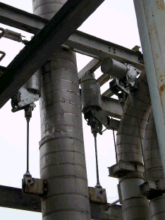
Figure 21 -- The plant installed new galvanized spring cans to replace deteriorated supports.
![]()
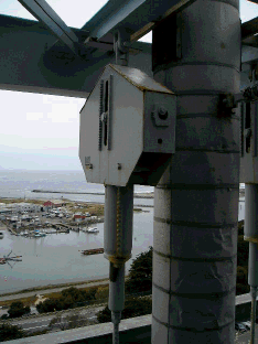
Figure 23 -- This is a close-up view of a simple spring support with the load indicator in the center of the polygon.

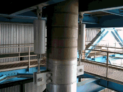
Figure 24 -- This is a photo of a new twin simple spring support. Note the load indicator.

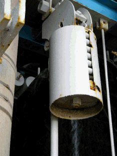
Figure 25 -- An older spring support that has been painted to prevent further corrosion.

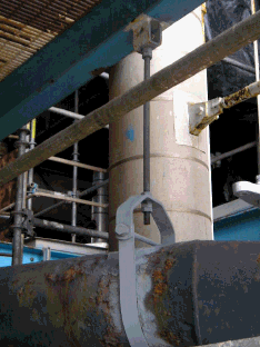
Figure 26 -- This is a photo of a new hanger and pipe support on an older pipe.

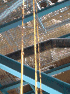
Figure 27 -- This is a photo of old rusted pipe support rods that have yet to be serviced or replaced.
Maintenance Standard 5 - Maintenance Personnel Knowledge and Skills
Maintenance personnel are trained and qualified to possess and apply the knowledge and skills needed to perform maintenance activities that support safe and reliable plant operation.
Operation Standard 5 - Operations Personnel Knowledge and Skills
Operations personnel are trained and qualified to possess and apply the knowledge and skills needed to perform operations activities that support safe and reliable plant operation.
Maintenance Standard 13 - Equipment Performance and Material Condition
Equipment performance and material condition support reliable plant operation. This is achieved using a strategy that includes methods to anticipate, prevent, identify, and promptly resolve equipment performance problems and degradation.
Assessment Guidelines
A. Plant equipment operates on demand.
B. Personnel exhibit a low tolerance for equipment and material condition problems by identifying deficiencies and advocating resolution.
C. Equipment performance monitoring is used to detect problems and degrading performance. Performance monitoring activities include the following:
1. In-service testing and in-service inspections
2. Collection and analysis of performance data and predictive monitoring information, such as thermal, hydraulic, chemical, electrical, acoustical, vibration, and mechanical parameters
3. Routine inspections and walkdowns
4. Analysis of performance history and trends
5. Aggregate reviews and analyses of performance data to determine equipment operability and availability
Maintenance Standard 14 - Engineering and Technical Support
Engineering activities are conducted such that equipment performance supports reliable plant operation. Engineering provides the technical information necessary for the plant to be operated and maintained within the operating parameters defined by plant design.
Assessment Guidelines
F. Engineering personnel monitor and evaluate equipment and system performance by examining and trending the results of condition-monitoring activities, reviewing equipment failure history, analyzing availability/reliability information, and performing system walkdowns. Follow-up actions, based on identified problems, trends, and root cause determinations, are timely and effective.
K. Engineering personnel use outside experts, such as vendor representatives or other utility expertise, as necessary, to resolve station problems. Appropriate controls are implemented to confirm the quality of the support and products supplied by non-plant organizations.
FINDING 2.3 - THE PLANT HAS NEITHER DETECTED EARLY SIGNS OF FAILURE NOR PREVENTED REPEATED FAILURES OF TURBINE BLADES
Moss Landing has neither detected early signs of failure nor prevented repeated failures of turbine blades in Units 1 and 2, a potential violation of Operation and Maintenance Standards. In October 2004, Unit 1's gas turbine compressor blades failed catastrophically despite instrumentation installed to detect the kind of vibrations that generally precede such failures. As a result of the failure, the plant was out-of-service for two months. In July 2006, at General Electric's (GE's) recommendation, Moss Landing inspected and found cracks in the compressor blades on all four gas turbines, after only 8,000 operating hours (Units 1 and 2 each have two gas turbines). By contrast, the manufacturer normally schedules inspections every 12,000 operating hours. While the cracks did not constitute a catastrophic failure, Moss Landing had to shut down the gas turbines one at a time for repair during a time of record power demand.
Under a fourteen-year service agreement, GE monitors the units remotely through the plant's on-site, centralized, computer control system. GE's "Power Smart System" is supposed to detect abnormal operating conditions in order to develop predictive maintenance schedules based on real time and historical operating data. Maintenance Standards require that equipment performance and monitoring and engineering technical support be sufficient to support reliable operations. Although Moss Landing hired GE to monitor its gas turbine, the plant cannot transfer all responsibility to a contractor.
LS Power and GE are investigating the failures, but refuse to release any information to Commission staff. In particular, they have not explained why the vibration monitoring system failed to detect early signs of blade failure.
Final Outcome and Follow-up
In response to this finding, the plant explained that it has taken reasonable steps to mitigate blade problems. First, prototype blades failed catastrophically and monitoring instruments detected no warning signs, such as excessive vibration, temperature or shaft displacement. Second, the plant is replacing the prototype blades with blades of the original design.
Moss Landing was one of the first plants to use the new prototype blades. The Plant Manager stated that the plant would not have used the new prototype blades if he had known that similar blade problems were discovered on other turbines. When the Auditor requested the Root Cause analysis of this event, the Plant Manager stated that GE will not release it because GE and the plant are in litigation.
The plant replaced Unit 2's prototype blades with blades of the original design in May 2007 and will install original blades on Unit 1 in 2008. In addition, the plant inspects compressor blades every 8,000 operating hours as opposed to GE's recommended frequency of 12,000 hours. The Plant Manager stated that Moss Landing will adhere strictly to that schedule to avoid any more failures. CPSD requests that the plant submit any reports that become available regarding the blade failure.
Maintenance Standard 5 - Maintenance Personnel Knowledge and Skills
Maintenance personnel are trained and qualified to possess and apply the knowledge and skills needed to perform maintenance activities that support safe and reliable plant operation.
Assessment Guidelines
C. On-the-job training and evaluation criteria are identified, completed, and documented before personnel are assigned to perform tasks independently.
G. Contract maintenance technicians and other non-plant maintenance personnel possess knowledge and skills equivalent to those of station maintenance personnel for their assigned functions and are task-qualified prior to independent work assignment.
Operation Standard 5 - Operations Personnel Knowledge and Skills
Operations personnel are trained and qualified to possess and apply the knowledge and skills needed to perform operations activities that support safe and reliable plant operation.
FINDING 2.4 - THE PLANT HAS NO RECORDS SHOWING THAT CONTRACTORS OR PLANT STAFF ARE CERTIFIED AND TRAINED IN HAZARDOUS WASTE AND ENVIRONMENTAL EMERGENCY RESPONSE
The plant has no records showing that contractors or plant staff are certified or trained in hazardous waste and environmental emergency response, a potential violation of Operation and Maintenance Standards. Nor does the plant make readily available to its staff a list of qualified emergency response contractors. In each case, the plant violates its own maintenance plan.
The plant cannot demonstrate that it verified any of its contractors' qualifications. The plant's contractors included hazardous waste haulers, demolition companies, welders, and bioassay companies. Operation and Maintenance Procedure (OMP) 7-18, which details criteria and qualifications for outside contractors, specifically requires that the plant maintain records of contractor qualifications. Plant staff stated that the plant keeps no copies on file of contractor qualification statements and certifications. The failure to keep these documents is contrary to the plant's OMP 7-18.
While Moss Landing has recently improved its procedure for contractor work, the plant still fails to maintain records for contractor certification and qualification. In July 2003, a demolition contractor accidentally ignited the residual oil in a disused oil tank, setting off a massive fire. The plant's investigation showed that the contractor failed to follow procedure and had failed to renew his certification. As a result of this incident, Moss Landing revised OMP 7-18 to specify steps the plant should take to better manage projects involving contractors. See Observation 3.4 for further discussion.
The plant lacks training records for either staff or contractors in hazardous materials handling and environmental emergency response. In this regard, the plant has failed to implement its own procedures. OMP 12-11.6.1.2 requires the plant to keep on file signed and dated records of all training. OMP 12-11.6.1.1 requires that all contractors take hazardous materials training each year. Such training is crucial at power plants, where employees and contractors routinely use dangerous materials and enter hazardous environments.
The plant does not make readily available to its staff a list of contractors qualified for hazardous waste disposal and environmental emergency response. This violates the plant's own procedure (OMP 15-16). The lack of a distributed list for those qualified to handle spills, toxic fires, and other situations is of particular concern. All plant personnel should be empowered to summon emergency help from appropriate resources without having to seek out references or authorization.
Finally, the plant's training procedures are not fully updated, and contain at least one inaccurate reference. OMP 7-44 CA 6.1 refers to the plant's training matrix, which shows what courses staff should take and how often, as "Exhibit A". In fact, there is no Exhibit A, and the training matrix is filed in another section of the plant's procedures.
Final Outcome and Follow-up
In response to this finding, the plant made a number of changes to its procedures for contractors and safety training. The plant now uses a "Contractor Qualification Form" to verify that contractors have appropriate training, certificates, bonds and insurance prior to being awarded a contract. The plant now keeps on file this form and supporting documents. The plant has also implemented new safety and quality control procedures. These procedures include a "Job Safety Analysis Sheet" for plant employees, and a "Contractor Safety Task Plan" for work performed by outside contractors. The plant uses a "Contractor Health and Safety Checklist" to review contractor work. As a result of the Audit, the plant discovered and repaired a faulty computer link in the Electronic Database System. The plant now keeps all training records and contractor information in the database. Finally, the plant relies on hazardous material handlers for all associated emergencies. The plant now makes the list of qualified handlers available to all plant personnel.
The plant now requires all contractors to fill out a "Contractor Qualification Form". The contractor must provide verification of job specific safety training, appropriate OSHA Certification(s), valid license(s) and bond(s), liability insurance information and emergency contact information. The form also requires the contractor to provide three years of OSHA injury information. The Auditor reviewed a contractor's file. The information was complete and these files now comply with the Code of Federal Regulations (CFR) and American National Standards Institute (ANSI) regulations. The plant has agreed to keep such files for all contractors.
The plant has implemented new procedures to improve worker safety and contractor quality control. Before beginning work, plant staff must submit or review a "Job Safety Analysis Sheet"; Contractors use a "Contractor Safety Task Plan". These forms detail the necessary steps and safety requirements to complete work. Plant staff also review contractor work on a daily or weekly basis (depending on the duration of the job or task) using a "Contractor Health and Safety Checklist". Plant staff randomly select "Job Safety Analysis Sheets" for review and discussion at weekly safety meetings.
As a result of this audit, the plant discovered and corrected an improper link in the plant's Electronic Documentation System. This electronic link allows the staff to input updated training records into the main computer and to simultaneously update individual employee files and specific contractor files. Plant staff demonstrated the repaired Electronic Documentation System, and showed that it now keeps current training records on file for all employees and contractors.
Regarding hazardous material training, the Plant Manager stated that the plant will not ask plant personnel to handle hazardous material during an emergency. Instead, the plant relies on hazardous material handlers, and now makes the list of qualified handlers available to all plant personnel.
Maintenance Standard 7 - Balance of Maintenance Approach
The maintenance program includes the proper balance of the various approaches to maintenance, e.g., preventive, predictive, or corrective. The approach is adequately documented with consideration of economics and reliability of equipment or components, and their affect on reliable operation of the unit. Operating experience is factored into the program. Maintenance procedures and documents should include the generation equipment and all those components owned by the generation owner directly connected to the plant that are an integral part of delivering power to the grid including fuel supply systems, electrical switchyards, transmissions lines, penstocks, flumes, exhaust system, etc.
FINDING 2.5 - THE PLANT LACKS A WRITTEN POLICY AND PROCEDURE FOR BOILER INSPECTION
The plant lacks a written policy and procedure for boiler inspections for Units 6 and 7, a potential violation of Maintenance Standards. The plant provided a one-page list of boiler components that should be inspected. However, the list fails to specify the scope, frequency or method of these inspections. The plant stated that it depends on boiler contractors to decide what tests to run and what specifically should be examined for each boiler component. The plant should maintain proper oversight over these inspections, and retain responsibility for their scope.
The plant hires contractors for annual, routine, boiler inspections, as well as occasional inspections that are more complete, but it is unclear why and on what basis the plant conducted these more complete inspections. The plant performed routine repairs recommended in inspection reports from 1995, 2001, and 2005.3
Final Outcome and Follow-up
In response to our finding, the plant has written a procedure to document its boiler inspection and maintenance program which includes an annual inspection program, historical repair records, acceptance criteria, and prioritizing of maintenance work.
The plant submitted its boiler inspection program entitled "Boiler Inspection and Maintenance Procedure" (Procedure No. MTM 7-50). This procedure prescribes routine in-house and scheduled inspections as specified by the original equipment manufacturer (OEM). The OEM's inspection and testing program is based on the plant's boiler furnace design and historical test data, which help identify problem areas for non-routine inspections. As a result of the OEM's inspection, the plant prioritizes work orders in the plant's Work Management System (Maximo). The plant specifies whether it will perform the work routinely, during outages or during major overhauls.
In addition to the furnace, the plant also inspects other systems as specified by Cal-OSHA. The plant's boiler inspection procedure identifies 19 related procedures including:
1. Safety valve repairs
2. Boiler hydro-testing procedure
3. Auxiliary steam valve repair
4. Low load valve maintenance
5. ID fan overhaul
6. FD fan overhaul
7. Hanger position settings
8. Spray water control & isolation valves
Maintenance Standard 1 - Safety
The protection of life and limb for the work force is paramount. The company behavior ensures that individuals at all levels of the organization consider safety as the overriding priority. This is manifested in decisions and actions based on this priority. The work environment, and the policies and procedures foster such a safety culture, and the attitudes and behaviors of individuals are consistent with the policies and procedures.
Operation Standard 1 - Safety
The protection of life and limb for the work force is paramount. GAOs have a comprehensive safety program in place at each site. The company behavior ensures that personnel at all levels of the organization consider safety as the overriding priority. This is manifested in decisions and actions based on this priority. The work environment and the policies and procedures foster such a safety culture, and the attitudes and behaviors of personnel are consistent with the policies and procedures.
Operation Standard 20 - Preparedness for On-Site and Off-Site Emergencies
The GAO plans for, prepares for, and responds to reasonably anticipated emergencies on and off the plant site, primarily to protect plant personnel and the public, and secondarily to minimize damage to maintain the reliability and availability of the plant.
Among other things, the GAO:
A. Plans for the continuity of management and communications during emergencies, both within and outside the plant,
B. Trains personnel in the emergency plan periodically, and
C. Ensures provision of emergency information and materials to personnel.
FINDING 2.6 - THE PLANT IS NOT UP-TO-DATE WITH EMERGENCY DRILLS AND RESPONSE MEASURES
The plant has not held emergency evacuation drills, installed an effective alarm system, installed an effective system accounting for all people onsite during emergencies, nor consistently designated emergency assembly areas, all potential violations of Operation and Maintenance Standards.
The plant has not held annual emergency evacuation drills as required by its own OMP. Moss Landing held its last full-scale evacuation drill on August 19, 2003. The Emergency Response Plan (ERP), as defined by the plant's OMP 15-7, requires an annual emergency response drill. This drill requires all personnel to "muster" at designated assembly areas (Figure 28). However, the Auditor learned that all subsequent drills involved only a few lead personnel, while other staff continued their work as usual. To assure adequate training for both staff and contractors, Moss Landing should hold an emergency evacuation drill for all people on site at the start of each major planned outage. If there is no planned outage during any year, the plant should hold an evacuation drill for all employees during that year.
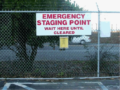
Figure 28 -- One of three emergency staging points or assembly areas. The information on the muster card, as seen here in a transparent enclosure, is to be updated semi-annually.
The plant has not installed an effective alarm system. During the August 19, 2003 drill, workers could not hear emergency sirens in some parts of the plant due to ambient noise, which can be very high in environments such as machine shops or turbine decks. In response, an internal 2003 review panel recommended installing new sirens. The plant scheduled but missed a December 2005 target date. According to the plant's security coordinator, the plant decided to delay the work "until after more demolition work was completed." This lack of action appears to indicate a low priority for staff safety. CPSD is also concerned that sirens alone maybe insufficient in noisy areas. The plant should install a system that can effectively alert all employees, consistent with OSHA requirements.4
The plant lacks a method of accounting for all people onsite during emergencies. First, the plant does not follow its own procedure. The Emergency Evacuation Plan (EEP), dated September 9, 2005, requires the plant to update muster cards semi-annually. Supervisors use these cards to take roll at each emergency assembly area. However, the plant confirmed that it missed the 2005 mid-year update. Moreover, the plant's muster card system is inadequate because cards updated only twice a year may not accurately identify all the people onsite at any one time.
Plant documents conflict regarding the number and location of emergency assembly areas. The "Guest Visitor and Contractor Information Pamphlet" shows two staging areas. The EEP and plot map show three emergency assembly areas. The plant should update these materials to ensure that all personnel know the locations of emergency assembly areas.
Final Outcome and Follow-up
In response to our finding, the plant conducted a full scale evacuation drill, improved its evacuation procedure and installed a new audible warning system (Figure 29). It updated all rosters (muster cards) and will continue to update them on a quarterly basis. However, CPSD requests that the plant make certain improvements as discussed below.
The plant conducted a full scale emergency evacuation drill in November 2006. According to an evaluation, the staff cannot hear sirens in the turbine building, 2nd floor administration offices and the assembly building. The plant must consider alternatives that can effectively alert employees in these areas.
Since the audit, plant staff has updated their "muster cards" and will continue to do so quarterly. The plant is considering additional steps such as using the sign-in list from the security gate, or placing ID card readers at assembly areas.
Finally, the plant has not verified whether it has updated all evacuation maps to include both primary and alternate assembly areas. In particular, the "Guest Visitor and Contractor Information Pamphlet" shows two assembly areas. The Emergency Evacuation Plan and Plot Map show three emergency assembly areas. The plant must make them consistent to ensure external rescue agencies and all plant personnel know the locations of all emergency assembly areas.
The plant should correct these deficiencies and submit a corrective report to CPSD by June 30, 2008.
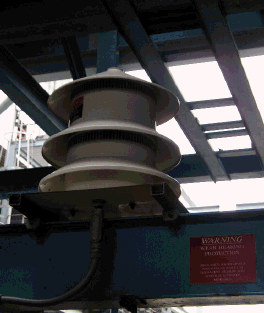
Figure 29 -- This is a photo of the new siren installed on Level 88 of Units 6 & 7.
Maintenance Standard 8 - Maintenance Procedures and Documentation
Maintenance procedures and documents are clear and technically accurate, provide appropriate direction, and are used to support safe and reliable plant operation. Procedures must be current to the actual methods being employed to accomplish the task and are comprehensive to ensure reliable energy delivery to the transmission grid.
Assessment Guideline
H. Procedures, documents, drawings, and other work-related references are readily accessible, authorized, clearly identified, controlled, technically accurate, and up to date.
Maintenance Standard 11 - Plant Status and Configuration
Station activities are effectively managed so plant status and configuration are maintained to support reliable and efficient operation.
Assessment Guideline
B.11 Documents affected by plant modifications such as drawings, procedures, and equipment indexes commonly used for system operation, tagouts, and maintenance, are updated before the modifications are turned over to operations.
FINDING 2.7 - THE PLANT LACKS A STANDARDIZED SYSTEM FOR STORING, RETRIEVING, AND REVISING PLANT DRAWINGS
The plant does not have a standardized system for storing, retrieving, and revising plant drawings that can be accessed easily by plant staff, potentially violating Maintenance Standards. The plant stores some documents electronically and others in hard copy. The Auditor found that plant staff did not know which system to use to find appropriate documents. Plant staff also lack training on how to access plant drawings. The plant does not keep track of updates to documents. Finally, the plant's library lacks a system to check documents in or out.
Some staff did not know how to find plant documents. The Auditor asked the Operations Team Leader and the Administrator of Drawing Documentation for a certified vendor print of the outline drawing of a pressure relief valve for Units 1 or 2's high pressure boiler drums. The two plant staff told the Auditor to speak to the "system owner" of the boiler, who is supposed to maintain the system's documentation and operating history. The boiler system's owner, however, was not able to locate that drawing. Further, he was not familiar with the system that is used for finding drawings.
Another staff person was familiar with the plant's system for storing drawings, but was unable to locate this particular drawing. He showed the Auditor a binder, supposedly given to all operating and maintenance personnel. That binder contained a list of all design drawings and their corresponding compact disks (CDs). Plant staff could download drawings from the CDs to their personal computers. The staffer was aware that the plant's library also stores hard copies of these drawings.
The plant's procedures do not describe how to label a document to show that it has been revised, nor do they describe how to change the document indexes. Plant staff could therefore access outdated and inaccurate drawings, which could cause errors in plant operation and maintenance.
Finally, the plant's library lacks an "out-card" procedure for drawings and manuals that staff
borrow. Loss of such materials could interfere with proper operation and maintenance of plant equipment.
Final Outcome and Follow-up
In response to our finding, the plant revised its document control procedure and increased document library staffing. Entitled "Library Maintenance and Use", the procedure tracks the latest documents revision and requires an out card to check out documents from its library. It also outlines the systemic steps required to list all outstanding documents, statuses, and current users, which ensures that staff uses the latest revision at all times. The plant also trained its entire technical team on how to access both electronic and hardcopy documents. The plant also added two full-time positions in 2006 to implement this new document control policy.
Maintenance Standard 8 - Maintenance Procedures and Documentation
Maintenance procedures and documents are clear and technically accurate, provide appropriate direction, and are used to support safe and reliable plant operation. Procedures must be current to the actual methods being employed to accomplish the task and are comprehensive to ensure reliable energy delivery to the transmission grid.
Assessment Guideline
A. The preparation, review, approval, and revision of procedures and documents are properly controlled and timely.
Operation Standard 7 - Operation Procedures and Documentation
Operation procedures exist for critical systems and states of those systems necessary for the operation of the unit including startup, shutdown, normal operation, and reasonably anticipated abnormal and emergency conditions. Operation procedures and documents are clear and technically accurate, provide appropriate direction, and are used to support safe and reliable plant operation. Procedures are current to the actual methods being employed to accomplish the task and are comprehensive to ensure reliable energy delivery to the transmission grid.
FINDING 2.8 - THE JOB DESCRIPTIONS AND TABLE OF CONTENTS OF THE PLANT'S WRITTEN PROCEDURES SHOULD BE UPDATED
The plant's procedures refer to positions that no longer exist at the plant, incorrectly assign duties, and contain inaccurate tables of contents, potentially violating Operation and Maintenance Standards.
Security procedures, entitled "Duke Energy Security - Security Performance Standards", refer to two positions which no longer exist at the plant: a Patrol Officer and an Elevator Officer. After these procedures were written, the Supervising Officer assumed the responsibilities of the Patrol Officer, and the plant eliminated the Elevator Officer position. The plant should update its security procedures to reflect these changes.
Similarly, the plant's procedures incorrectly assign duties to an administrative assistant. OMP 1-3 Section 5.1 states:
"The appointed Administrative Assistant will conduct an annual audit of each volume and revise as necessary to assure that its contents are up-to-date. Completion of this audit will be documented in a memorandum to the Plant Manager to be received by the date above."
The plant now assigns this duty to the "system owner". The plant should update OMP 1-3 to reflect these changes.
Finally, the master table of contents for the plant's procedures, contains errors and omissions, and conflicts with the table of contents for a specific volume. One table shows that OMP 11-4 is entitled "Outage Planning", while another table shows that OMP 11-15 in fact bears that title.5 Further, the master table omits section OMP 1-4. The plant should correct these references.
Final Outcome and Follow-up
In response to our finding, the plant removed from its procedures reference to positions that no longer exist, updated the process for maintaining procedures, and eliminated discrepancies between the Master Table of Contents and the table of contents for each volume.
In OMP 3-19A, the plant removed Elevator Officer and the Supervising Officer and included the Patrol Officer and his/her responsibilities. The procedure clearly states that the Patrol Officer, not the Supervising Officer, is responsible for patrolling the site.
The plant revised OMP 1-3, Section 5.1 to state that system owners are responsible for maintaining procedures within their respective volumes. This procedure has been moved to OMP 1-1, Section 4.0.
Lastly, the Auditor verified that the plant revised the Master Table of Contents, OMP 1-1, to eliminate discrepancies between the Master Table of Contents and the table of contents for specific volumes.
Maintenance Standard 8 - Maintenance Procedures and Documentation
Maintenance procedures and documents are clear and technically accurate, provide appropriate direction, and are used to support safe and reliable plant operation. Procedures must be current to the actual methods being employed to accomplish the task and are comprehensive to ensure reliable energy delivery to the transmission grid.
Maintenance Standard 3 - Maintenance Management and Leadership
Maintenance managers establish high standards of performance and align the maintenance organization to effectively implement and control maintenance activities.
Assessment Guidelines
A. Leadership and Accountability
1. High standards of performance are established and reinforced for maintenance activities. Personnel are held accountable for implementing these standards. Shortfalls in meeting expectations are evaluated, understood, and addressed promptly.
2. Maintenance managers demonstrate a broad knowledge of their areas of responsibility and effectively integrate maintenance organization actions with the functions and activities of other appropriate station and company organizations.
FINDING 2.9 - THE PLANT HAS NOT COMPLETELY IMPLEMENTED ITS COMPUTERIZED INVENTORY SYSTEM AS REQUIRED BY ITS OWN PROCEDURES
Procedure OMP 5-0 states that the plant uses a computer database called Maximo to track and manage spare inventory. However, the Auditor observed that this part of the procedure has not been fully implemented, a potential violation of Maintenance Standards.
The Maintenance Manager stated that the plant uses Maximo to manage spare inventory. When inventory falls below preset levels or becomes obsolete, the system notifies staff to allow timely restocking of the item. The Auditor asked for a demonstration and asked for an inventory printout from the system. The Manager was unable to respond to the Auditor's request. At the time, he explained that he lacked the security clearance to access the information.
Instead, the Maintenance Manager pointed out that inventory binders are available in each of the three warehouses. See Observation 3.8. Aside from this practice, the Auditor saw no evidence that the plant uses Maximo to track and manage inventory, which ultimately is contrary to its own procedure.
The Auditor telephoned the Maintenance Manager in July 2006. At the time, the Manager still lacked access to the system. However, he stated that in fact the plant is transitioning from paper to electronic inventory tracking. He said that not all spares are currently tracked in Maximo; a part is added to the system over time only when that part is re-ordered. This confirmed that the plant's practice is inconsistent with its written procedure.
Final Outcome and Follow-up
In response to our finding, the plant confirmed that its newly assigned Maintenance Manager has full Maximo access, and that plant staff use the system to control the plant's inventory.
First, the plant stated that the person the Auditor interviewed was not the Maintenance Manager. LS power, which had just bought the plant, had not yet named a Maintenance Manager. A person of a higher authority could have provided the information and satisfied the Auditor's request.
Then in January 2007, the plant provided a copy of its inventory report. The report contained inventory information such as item description, bin location, and current balance. Plant staff had generated the report from Maximo and the report conformed to plant procedure.
During the meet and confer meeting, the Auditor met with the Maintenance Manager and asked him to verify his Maximo access. The manager logged into the database and showed the Auditor how he runs inventory reports. That report was consistent with the one that the plant had submitted in January.
Maintenance Standard 13 - Equipment Performance and Material Condition
Equipment performance and material condition support reliable plant operation. This is achieved using a strategy that includes methods to anticipate, prevent, identify, and promptly resolve equipment performance problems and degradation.
Assessment Guidelines
A. Plant equipment operates on demand.
B. Personnel exhibit a low tolerance for equipment and material condition problems by identifying deficiencies and advocating resolution.
C. Equipment performance monitoring is used to detect problems and degrading performance. Performance monitoring activities include the following:
1. In-service testing and in-service inspections
2. Collection and analysis of performance data and predictive monitoring information, such as thermal, hydraulic, chemical, electrical, acoustical, vibration, and mechanical parameters
3. Routine inspections and walkdowns
4. Analysis of performance history and trends
5. Aggregate reviews and analyses of performance data to determine equipment operability and availability
FINDING 2.10 - THE PLANT DOES NOT TEST MOTOR INSULATION RESISTANCE AT INTERVALS PRESCRIBED IN THE PLANT'S PREDICTIVE MAINTENANCE SCHEDULE
The plant does not test motors regularly as prescribed in the plant's own maintenance plan, a potential violation of Maintenance Standards. Predictive Maintenance Work Orders 3244, 3245 and 3246 call for weekly testing (meggering) of the insulation resistance of the 4160 Volt and 480 Volt motors of Units 6 and 7. Between July and December 2005, the plant sometimes let more than a month pass between tests. This interval is not in conformance with the plant's own Predictive Maintenance Program.
Final Outcome and Follow-up
In response to our finding, the plant installed a system that continuously meggers motors, eliminating the need for weekly manual meggering. The plant submitted a letter from Shaw Engineering stating that the Meg-Alert system may substitute for manual meggering provided that plant staff make weekly rounds to assure that each Meg-Alert monitor is functioning. The plant stated that a revised work order for such weekly rounds was submitted to CPSD in Attachment 2.10A. However, Attachment 2.10A only contains the letter from Shaw Engineering which is numbered page 1 of 2. Page 2, presumably the work order, is missing. CPSD requests that the plant send the revised work order to CPSD no later June 30, 2008.
Operation Standard 21 - Plant Security
To ensure safe and continued operations, each GAO provides a prudent level of security for the plant, its personnel, operating information and communications, stepping up security measures when necessary.
FINDING 2.11 - THE PLANT HAS DELAYED INSTALLATION OF RECORDING EQUIPMENT FOR SECURITY CAMERAS
The plant has delayed the installation of video recorders for the plant's six security video cameras, a potential violation of Operation Standards. A 2003 report by Duke recommended installation of a closed-circuit television system at the plant, along with video recorders. The plant stated in a 2004 report to Duke that the installation was underway. By December 2005, the plant had installed the video cameras but not the recording equipment. At that time, plant staff stated that the plant would complete the work in 2006. Failure to install recording equipment may make it difficult to detect, track, and prosecute any trespassers on plant property.
Final Outcome and Follow-up
During the meet and confer meeting, the Auditor verified that the plant has installed a recorder for its video cameras. Located adjacent to the control room, the recorder retains images up to 30 days, and can save information to DVD.
This section describes parts of the audit where CPSD staff observed no violations of standards.
Operation Standard 21 - Plant Security
To ensure safe and continued operations, each GAO provides a prudent level of security for the plant, its personnel, operating information and communications, stepping up security measures when necessary.
The plant provided two studies of security, and has instituted security measures comparable to those at other fossil fuel power plants in California. The Auditor reviewed two reports. The 2003 Security Vulnerability Mitigation Review, issued by Duke Energy North America Security in Houston, is an internal report. The Security Risk Assessment Report, dated December 20, 2002, is a four-page report issued by Concept Security (Marina, California).
Some recommendations in the consultant's Risk Assessment Report have been implemented at the plant, but others have not for economic reasons.
The plant has addressed all issues in Duke's own Security Vulnerability Mitigation Review,
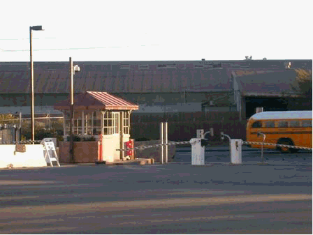
Figure 30 -- Guard station at the main gate along Dolan Road.
Maintenance Standard 1 - Safety
The protection of life and limb for the work force is paramount. The company behavior ensures that individuals at all levels of the organization consider safety as the overriding priority. This is manifested in decisions and actions based on this priority. The work environment, and the policies and procedures foster such a safety culture, and the attitudes and behaviors of individuals are consistent with the policies and procedures.
Operation Standard 1 - Safety
The protection of life and limb for the work force is paramount. GAOs have a comprehensive safety program in place at each site. The company behavior ensures that personnel at all levels of the organization consider safety as the overriding priority. This is manifested in decisions and actions based on this priority. The work environment and the policies and procedures foster such a safety culture, and the attitudes and behaviors of personnel are consistent with the policies and procedures.
Maintenance Standard 3 - Maintenance Management and Leadership
Maintenance managers establish high standards of performance and align the maintenance organization to effectively implement and control maintenance activities.
Assessment Guideline
D.6 Managers continuously and effectively monitor and assess the performance of maintenance activities, with particular attention to general area housekeeping
Maintenance Standard 18 - Maintenance Facilities and Equipment
Facilities and equipment are adequate to effectively support maintenance activities.
Assessment Guideline
C. Work areas are maintained in a clean and orderly condition.
Except for hazards described in Finding 1.1, the plant was generally well-maintained. For instance, the lab areas in Units 1 and 2, as well as the main chemistry laboratory in the Administration Building, were clean and tools and equipment appeared to be in place. Safety precautions such as secondary containment and safety equipment were present. A "remote control room" for Units 6 and 7 stores reference materials and houses some monitoring equipment; it was clean and well-organized.
The Operations Team Leader and the Auditor walked through Units 1 and 2. All containers for liquids appeared to be properly stored and surrounded by secondary containment. Secondary containment, a tray or barrier surrounding dangerous or corrosive chemicals, is a safety precaution to prevent chemicals from leaking into the workspace and coming into contact with plant staff. The water chemistry area was clean. Only a few chemicals were on benches or table tops. The lab was orderly and well kept. Personal safety equipment was visible and well stocked. The Operations Team Leader said that there is an incentive program for staff to maintain plant cleanliness. After a monthly evaluation and walk-down by supervisors, the plant rewards the best crew with a barbeque.
The Auditor also visited the main chemistry laboratory in the Administration Building. He found an extensive supply of chemical spill and chemical containment supplies available. The laboratory was very orderly and clean. All caustic liquids were kept in secondary containments and properly stored and labeled.
Maintenance Standard 1 - Safety
The protection of life and limb for the work force is paramount. The company behavior ensures that individuals at all levels of the organization consider safety as the overriding priority. This is manifested in decisions and actions based on this priority. The work environment, and the policies and procedures foster such a safety culture, and the attitudes and behaviors of individuals are consistent with the policies and procedures.
Operation Standard 1 - Safety
The protection of life and limb for the work force is paramount. GAOs have a comprehensive safety program in place at each site. The company behavior ensures that personnel at all levels of the organization consider safety as the overriding priority. This is manifested in decisions and actions based on this priority. The work environment and the policies and procedures foster such a safety culture, and the attitudes and behaviors of personnel are consistent with the policies and procedures.
Operation Standard 20 - Preparedness for On-Site and Off-Site Emergencies
The GAO plans for, prepares for, and responds to reasonably anticipated emergencies on and off the plant site, primarily to protect plant personnel and the public, and secondarily to minimize damage to maintain the reliability and availability of the plant.
Among other things, the GAO:
A. Plans for the continuity of management and communications during emergencies, both within and outside the plant,
B. Trains personnel in the emergency plan periodically, and
C. Ensures provision of emergency information and materials to personnel.
The Auditor confirmed appropriate installation of safety drench showers and eyewash stations during the tour of the facility. He also found emergency equipment, which was appropriate to each site-specific hazard, readily available and accessible. Inspection tags were evident and emergency equipment appeared to be well-maintained.
The Health and Safety Specialist is a registered Emergency Medical Technician and trains staff in medical emergencies and general safety protocol. All staff members are trained in general First Aid and Cardiopulmonary Resuscitation (CPR). Fifty percent are trained with Automated External Defibrillators (AEDs).
The Auditors attended the Weekly Safety Training Meeting led by the Health and Safety Specialist. All staff members are required to attend these weekly meetings. Topics typically cover a wide variety of safety issues. This week's topic was CPR and use of the AED. The class was well-structured and training supplies were adequate. This was a hands-on class and participation by all was required.
The Auditor also attended the 07:00 hour tailboard meeting where one of the agenda items was a safety review of "Caution Barricades and Asbestos Containment". The facilitator encouraged discussion. However, although the Auditor found that these aspects of safety planning and training were thorough, there were some problems in applying this safety training in practice. As noted in Finding 1.1, the Auditor observed deteriorating insulation that was not properly contained or isolated.
Maintenance Standard 5 - Maintenance Personnel Knowledge and Skills
Maintenance personnel are trained and qualified to possess and apply the knowledge and skills needed to perform maintenance activities that support safe and reliable plant operation.
Assessment Guideline
G. Contract maintenance technicians and other non-plant maintenance personnel possess knowledge and skills equivalent to those of station maintenance personnel for their assigned functions and are task-qualified prior to independent work assignment.
Operation Standard 15 - Communications and Work Order Meetings
The availability of the generating asset and safety of personnel is ensured during the execution of work orders by adequate communications and meetings, which may be scheduled or as needed, to review work plans with all affected personnel before work begins. Clear lines of communication exist between personnel responsible for operations, maintenance and engineering groups.
Among other things:
A. The GAO prepares and maintains a procedure for review of work plans through communications and work order meetings at the facility.
B. Work is analyzed to determine what personnel, components, and systems are affected.
C. Affected personnel meet before work begins to define the work, identify safety issues, to minimize the impact on plant operation, and to determine the need for further meetings.
D. Personnel are trained in and follow the procedure.
On July 8, 2003, a contractor accidentally ignited residual oil while using a cutting torch to dismantle a disused oil tank. The fire sent clouds of smoke across the surrounding area for several hours. When asked what lessons were learned from the incident investigation, the Production Supervisor said that, prior to any work, the plant should:
1) Require contractors to file more detailed work plans; and
2) Review and maintain current certification of all skilled workers.
Once the work begins, the plant should:
1) Oversee work more tightly;
2) Use field inspection checklists; and
3) Hold daily tailboard meetings to review progress and future work.
On September 1, 2005, the plant revised OMP 7-18 to implement these changes, and reviewed the qualifications of existing demolition contractors. However, the plant still does not maintain records on contractor certification, qualifications or training, as described in Finding 2.4.
Maintenance Standard 6 - Training Support
A systematic approach to training is used to achieve, improve, and maintain a high level of personnel knowledge, skill, and performance.
Operation Standard 6 - Training Support
A systematic approach to training is used to achieve, improve, and maintain a high level of personnel knowledge, skill, and performance. Each GAO provides a site-specific training program including on-the-job training, covering operations, including reasonably anticipated abnormal and emergency operations. Personnel are trained commensurate with their duties.
The plant uses an electronic database called "Conductor Orchestrated Training" to track certification and training records of all staff and contractors. Supervisors and team leaders are responsible for assuring all staff receives training and recertification as needed. The computer program allows supervisors and team leaders to see who is in need of training and recertification. The Auditor reviewed several contractor's and crew member's files to confirm that the system operated as described. However, the plant lacked records of contractor certification as well as training in hazardous waste and environmental emergency response. See Finding 2.4.
Moss Landing encourages professional staff development through continuing education and tuition reimbursement. Training is available through onsite computer-based training programs, through computer simulators and at local Community Colleges. The plant maintains a simulator for Units 6 and 7 in the control room in order to train operators. The plant uses Question and Answer sheets to evaluate training sessions and to get feedback and suggestions.
Archived records date back five years and are kept on the second floor of the Administration Building. These records pre-date the computerized database. However, records are missing for contractor and staff training in hazardous materials and environmental emergency response. See Finding 2.4.
Operation Standard 17 - Records of Operation
The GAO assures that data, reports and other records reasonably necessary for ensuring proper operation and monitoring of the generating asset are collected by trained personnel and retained for at least five years, and longer if appropriate.
The plant keeps archived records on the second floor of the Administration Building. The Auditor selected about thirty files at random, and found records of training, certification and environmental compliance going back at least five years. The plant now keeps such records on a computerized database. However, these archives lack records for contractor and staff training in hazardous materials and environmental emergency response. See Finding 2.4.
Maintenance Standard 7 - Balance of Maintenance Approach
The maintenance program includes the proper balance of the various approaches to maintenance, e.g., preventive, predictive, or corrective. The approach is adequately documented with consideration of economics and reliability of equipment or components, and their affect on reliable operation of the unit. Operating experience is factored into the program. Maintenance procedures and documents should include the generation equipment and all those components owned by the generation owner directly connected to the plant that are an integral part of delivering power to the grid including fuel supply systems, electrical switchyards, transmissions lines, penstocks, flumes, exhaust system, etc.
Maintenance Standard 9 - Conduct of Maintenance
Maintenance is conducted in an effective and efficient manner so equipment performance and material condition effectively support reliable plant operation.
Maintenance Standard 10 - Work Management
Work is identified and selected based on value to maintaining reliable plant operation. Work is planned, scheduled, coordinated, controlled, and supported with resources for safe, timely, and effective completion.
Volume 11, Section 16 of the plant's maintenance procedures state that the plant uses a mix of preventive and predictive maintenance. The plant uses operating experience to determine how to balance the two approaches. In general, the plant performs at a fixed interval low-cost maintenance, such as changing filters on pumps and fans. The plant uses ultrasonic testing, vibration and oil analysis, thermography, and other available technologies to determine the need for higher cost maintenance, such as that performed on major equipment like the boiler and steam turbine.
Section 1 of the maintenance procedure describes how repairs are scheduled and tracked using a work management database called Maximo. Plant staff can request maintenance by creating a work order via computer terminals throughout the plant. The work order is sent to the planning group where all work necessary at the plant is prioritized and scheduled. Upon approval, the planning group generates a work order package, which contains diagrams, instructions, and other materials necessary for crew to complete work safely and effectively. After the work is completed, any relevant information (including any comments from the staff performing the work) will be recorded in Maximo.
To verify that the plant follows its procedures, the Auditor attended two daily meetings, one on priorities, and one on work planning. The Maintenance Manager distributed two handouts at priorities meeting, listing backlogged mechanical and electrical repairs, respectively. He gathered updates from crew members and discussed whether any work orders needed to be reprioritized. In the planning meeting, the Maintenance Manager reviewed work order packages to ensure that crew members were well-informed and properly-equipped for their field work.
The Maintenance Manager demonstrated Maximo for the Auditor. The Manager retrieved a work order for the replacement of an air filter on Unit 6's forced draft fan. The Auditor verified Maximo entries showing that the plant had replaced the filter every three months as scheduled. The Manager then created a list of preventive maintenance items from the database. The list had at least 500 maintenance items, ranging from cleaning the motor filters on the circulating water pumps to cleaning the control room. Some of these maintenance activities were performed annually, others were performed monthly, and some were performed weekly.
Maintenance Standard 12 - Spare Parts, Material and Services
Correct parts and materials in good condition, are available for maintenance activities to support both forced and planned outages. Procurement of services and materials for outages are performed in time to ensure materials will be available without impact to the schedule. Storage of parts and materials support maintaining quality and shelf life of parts and materials.
The Auditor visited each of the plant's three warehouses. One serves Units 6 and 7, a separate warehouse serves Units 1 and 2, and a third warehouse stores replacement parts for the gas turbines. All three warehouses were in order (Figure 31). Each warehouse maintains a binder listing that warehouse's spare parts and materials along with the bin in which they are stored. The Auditor randomly selected a component from that list and asked the Warehouse Manager to locate it in storage. The Manager located the part without problem.
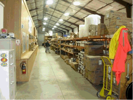
Figure 31 -- One of the three warehouses onsite; stocks are organized and labeled with bin location.
Maintenance Standard 8 - Maintenance Procedures and Documentation
Maintenance procedures and documents are clear and technically accurate, provide appropriate direction, and are used to support safe and reliable plant operation. Procedures must be current to the actual methods being employed to accomplish the task and are comprehensive to ensure reliable energy delivery to the transmission grid.
The Auditor reviewed printed copies of the plant's OMPs as well as their electronic counterparts in the plant's Intranet. The Intranet is available to all employees. The Auditor received an overview of Maximo, reviewed welder qualification records, interviewed team leaders, and found that in general, the procedures are current and being employed. In particular, the Auditor reviewed the following documents:
1. Volume 1 - Procedure Guidelines (procedures 1-2, 1-3, and 1-4)
2. OMP 11-7, Completion of Work Orders and Improvements
3. OMP 11-13, Welding Certification Program6
4. OMP 11-15, Outage Planning
5. Original Equipment Manufacturer manuals on the Intranet for Units 1 and 2
Maintenance Standard 9 - Conduct of Maintenance
Maintenance is conducted in an effective and efficient manner so equipment performance and material condition effectively support reliable plant operation.
Maintenance Standard 11 - Plant Status and Configuration
Station activities are effectively managed so plant status and configuration are maintained to support reliable and efficient operation.
Assessment Guidelines
A.4 Operations personnel are responsible for assessing the operability of important equipment. Information about equipment deficiencies, existing plant configuration, and the design bases for the equipment is used in the assessment. Other personnel, such as in engineering, maintenance, or chemistry, provide technical support for the assessment.
A.8 Independent (or concurrent, if appropriate) verification of component position is performed for equipment important to safety and/or critical to reliable plant operation.
The Auditor observed various station activities during the plant site visit, which included routine preventative maintenance as well as operations in the Control Room, such as the monitoring of cation readings and alarms.
Plant crews were actively involved in routine preventive maintenance, including Unit 6 condenser maintenance and repairs. Plant staff cleaned out condenser tubes on the plant side and divers worked to clean out the cooling water intake tunnels to prevent clogging of the tunnels. The Auditor saw crews painting and maintaining the main feedwater pumps to Units 6 and 7 to prevent corrosion and decay.
The Auditor spent an hour observing operations staff in the Control Room, and observed two alarms during this period: a high cation reading and an hydrogen pump alarm. The operators acknowledged the alarms and sent an operator to investigate. Plant staff investigated and cleared these alarms within 20 to 30 minutes. The operator determined that a faulty metering box caused the high cation reading. Staff checked and reset the hydrogen pump, which resumed operation. Operators created a work order to replace the faulty metering box.
Maintenance Standard 11 - Plant Status and Configuration
Station activities are effectively managed so plant status and configuration are maintained to support reliable and efficient operation.
Assessment Guideline
A.9 Checklists or other comparable means are used to verify that proper conditions are established for each mode of plant operation and for mode changes.
Maintenance Standard 14 - Engineering and Technical Support
Engineering activities are conducted such that equipment performance supports reliable plant operation. Engineering provides the technical information necessary for the plant to be operated and maintained within the operating parameters defined by plant design.
Assessment Guideline
G. Comprehensive in-service and post modification/maintenance testing is conducted so that equipment necessary for safe and reliable plant operation will perform within established limits. The testing program includes a description of scope and responsibilities, scheduling mechanisms, test procedures, and methods for program updates.
Operation Standard 28 - Equipment and Systems
GAO complies with these Operation Standards (1-27) considering the design bases (as defined in the Appendix) of plant equipment and critical systems. The GAO considers the design basis of power plant equipment when as required by other standards it, among other things:
A. Establishes procedures for the operation of critical systems at each unit (Ref. Standard No. 7).
B. For each system, identifies critical parameters that require monitoring (Ref. Standard No. 8 and 13).
C. For each critical parameter, establishes values at which to increase observation of the system or take actions to protect it (Ref. Standard No. 8 and 13).
D. Assures that systems are monitored and actions are taken. (Ref. Standard 8 and 13)
E. Establishes parameters for operation during periods of stress or shortage on the state's electric grid (Ref. Standard No. 9 and 19).
F. Assures that personnel operating critical systems are trained and qualified (Ref. Standard No. 6).
The Auditor spoke to the Operations Team Leader about the overall fire protection system. He stated that the plant's fire protection system has two raw water storage tanks and three diesel fire pumps. The steam and gas turbine generators are equipped with a water deluge suppression system. The Auditor also confirmed and verified this arrangement by comparing the team leader's description with the plant's drawing of the fire protection system flow diagram. The team leader stated that the plant is self-insured. However, in accordance with normal industry practice, the plant certifies its own equipment by performing a monthly test and inspection of their fire protection system equipment per California Administrative Code Title No. 19 and National Fire Protection Association requirements. The Auditor confirmed and reviewed the annual and monthly routine inspection checklists for the fire protection system and found these records to be in order.
Operation Standard 13 - Routine Inspections
Routine inspections by plant personnel ensure that all areas and critical parameters of plant operations are continually monitored, equipment is operating normally, and that routine maintenance is being performed. Results of data collection and monitoring of parameters during routine inspections are utilized to identify and resolve problems, to improve plant operations, and to identify the need for maintenance. All personnel are trained in the routine inspections procedures relevant to their responsibilities.
Among other things, the GAO creates, maintains, and implements routine inspections by:
A. Identifying systems and components critical to system operation (such as those identified in the guidelines to Standard 28).
B. Establishing procedures for routine inspections that define critical parameters of these systems, describe how those parameters are monitored, and delineate what action is taken when parameters meet alert or action levels.
C. Training personnel to conduct routine inspections.
D. Monitoring routine inspections.
Maintenance Standard 13 - Equipment Performance and Material Condition
Equipment performance and material condition support reliable plant operation. This is achieved using a strategy that includes methods to anticipate, prevent, identify, and promptly resolve equipment performance problems and degradation.
Assessment Guideline
C. Equipment performance monitoring is used to detect problems and degrading performance. Performance monitoring activities include the following:
1. In-service testing and in-service inspections
2. Collection and analysis of performance data and predictive monitoring information, such as thermal, hydraulic, chemical, electrical, acoustical, vibration, and mechanical parameters
3. Routine inspections and walkdowns
4. Analysis of performance history and trends
5. Aggregate reviews and analyses of performance data to determine equipment operability and availability
The Auditor reviewed the logs recorded by outside (that is, roving) operators at all plant units. These operators make rounds four times each day, recording on log forms the measurements and readings of key parameters for major equipment and systems. For example, for one of Unit 1's HRSGs, the operator checks motor oil levels, pump oil levels, temperatures of the cooling water at the inlets and outlets of the inboard and outboard stuffing boxes, and flow indicators for feedwater. The forms specify the normal operating range for each reading. The plant's Digital Control System (DCS) monitors many plant components continuously and automatically; if these measurements fall out of acceptable ranges, an alarm sounds in the Control Room. Plant staff said that technicians take vibration measurements on the feedwater pump every 3 months with Micrologger, a hand-held recording device. At the time of the audit, the software that downloads the data from Micrologger to a computer was not working. The software vendor is in the process of correcting the problem.
Another Auditor accompanied a roving operator on the morning walk-down and inspection of Units 6 and 7. The walk-down included reading instruments at major systems, including the fuel system, boiler system, turbine, generator, and electrical systems. However, at least in this case the operator concentrated on taking readings, and did not note problems in the plant environment, such as standing water, deteriorating insulation, and trip and fall hazards as described in Finding 1.1.
Maintenance Standard 15 - Chemistry Control
Chemistry controls optimize chemistry conditions during all phases of plant operation and system non-operational periods.
Assessment Guidelines
A. Chemistry specifications and methods of control are clearly established for systems requiring corrosion control. Chemical and biological contaminants are kept to a practical and achievable minimum level.
B. Sufficient parameters are measured to detect abnormal conditions or changes to conditions. Limits for key parameters are established based on industry technical guidance, where applicable.
C. Action levels are established and emergency actions are planned and implemented for key chemistry parameters. Out-of-specification conditions and abnormal chemistry are corrected in a timely manner.
D. Chemistry parameters are maintained within specified bands. Sampling frequency provides timely detection of chemistry trends.
E. Corrective actions are taken before chemistry specifications are exceeded.
F. Bulk chemicals, laboratory chemicals, corrosive agents, organic chemicals, and cleaning agents are controlled to prevent improper use or inadvertent introduction into plant systems.
G. Chemicals and media such as resins are maintained and controlled to preserve their physical and chemical properties.
H. System leaks that affect chemistry conditions are promptly investigated, and actions are taken to preserve material condition.
I. System chemistry controls are evaluated and adjusted, as necessary, to improve plant material condition.
J. The effectiveness of water processing equipment is routinely evaluated, and adjustments are made to improve performance.
K. Chemistry specifications and methods of control are clearly established for systems requiring corrosion control during non-operational periods, including system startup and shutdown.
L. Equipment is soaked and flushed, as needed, to remove contaminants prior to corrosion control measures being established, after system cleaning, and prior to startup.
M. Schedules for plant startup and shutdown contain hold points to verify that system chemistry is within control limits.
N. Chemistry data is routinely reviewed and trended to identify chemistry control problems and analytical errors.
O. On-line monitor results are routinely compared with laboratory results. Analytical data is compared to calculated or theoretical data. Investigations are performed when the data does not correlate.
P. The effectiveness of system chemistry control is determined by measures such as component inspections or corrosion monitoring of selected plant systems.
Q. On-line chemistry monitors accurately measure, record, and provide alarms for key parameters, where needed. On-line monitors are properly maintained and calibrated.
Operation Standard 28 - Equipment and Systems
Operation Standard 28 - Equipment and Systems
GAO complies with these Operation Standards (1-27) considering the design bases (as defined in the Appendix) of plant equipment and critical systems. The GAO considers the design basis of power plant equipment when as required by other standards it, among other things:
A. Establishes procedures for the operation of critical systems at each unit (Ref. Standard No. 7).
B. For each system, identifies critical parameters that require monitoring (Ref. Standard No. 8 and 13).
C. For each critical parameter, establishes values at which to increase observation of the system or take actions to protect it (Ref. Standard No. 8 and 13).
D. Assures that systems are monitored and actions are taken. (Ref. Standard 8 and 13).
E. Establishes parameters for operation during periods of stress or shortage on the state's electric grid (Ref. Standard No. 9 and 19).
F. Assures that personnel operating critical systems are trained and qualified (Ref. Standard No. 6).
Assessment Guidelines
G. Boiler Chemistry
1. General Guidelines
Personnel are trained in the operation of the chemical injection systems, their controls and indicators, permissives, alarms and trips. The importance of maintaining sufficient sample flow rates and the conditions for notifying a chemist are clearly described in operating procedures.
2. Detailed Guidelines
In developing its plans, procedures, and training programs to comply with the Operating Standards, the GAOs should consider the following issues.
a. Appropriate training in boiler blow down system and its impact to overall boiler water chemistry, flow limits, drum water levels, and boiler makeup water system.
b. The chemical injection method, injection locations, and reasoning behind using chemical processes such as oxygen scavenger, phosphate, sodium hydroxide, trisodium phosphate, and ammonia.
c. Identification of parameter ranges for all monitored and controlled boiler water parameters and action steps for out of range values.
The Auditor observed the chemistry lab and the activities of the lab technician to determine if a formal boiler feedwater chemistry program is in place. The program at Units 1 and 2 for boiler feedwater chemistry is entitled "Moss Landing Power Plant, HRSG Operating Chemistry Programs, Volume 10, Procedure E-204". The plant appears to follow its procedures and to maintain equipment adequately.
The plant chemist is responsible for water chemistry for all four units. The Auditor asked the plant chemist how he monitors the boiler feedwater chemical parameters for the boiler feedwater. The chemist stated that a DCS automatically monitors feedwater set levels for various parameters such as potassium and pH levels, and will set off alarms when measurements exceed acceptable levels. In addition, the chemist and technicians take "grab samples" two times a day to verify the data collected by the DCS. The Auditor observed a chemical technician analyzed grab samples for silica, phosphate, and chlorides and recorded the results on a daily checklist. The chemical technician noted a high level of phosphate in the feedwater (although not high enough to trip the DCS alarm) and called the control room operator to initiate a "blow-down" to remove phosphates and other impurities from the feedwater.
The plant chemist stated that the plant should consider cleaning the boilers chemically if a massive tube leak contaminates a boiler and feedwater quality subsequently continues to be poor. Further, during the annual inspection of the boilers for Units 6 and 7, the plant cuts and removes a section of the superheater tubes. If deposits to the interior of the tubes exceed certain levels, chemical cleaning is required. The plant does not take similar samples from the boilers for Units 1 and 2 because those boilers are still relatively new and unlikely to require chemical cleaning. At some point, however, the plant should develop criteria to determine the need to clean these boilers.
The chemistry laboratory as well as the equipment for storage, pumping, and injection of chemicals into the feedwater appeared to be in good order. The chemistry laboratory contains the sample panel, sample coolers, testing equipment, and chemical reagents used for analyzing feedwater samples. The laboratory appeared to be very well-organized and clean. All chemicals bore labels. Lighting and ventilation in the laboratory's fume hood functioned correctly. An eyewash station was located inside the laboratory and both eyewash and shower stations were located just outside the chemistry lab. Chemical storage and pumps were surrounded by a curbed secondary containment for chemical spills.
The Auditor inspected a binder located inside the lab that contained the Material Safety Data Sheets and confirmed that all write-ups concerning major feedwater chemicals were inserted in the binder, available for use in case of an emergency.
Maintenance Standard 16 - Regulatory Requirements
Regulatory compliance is paramount in the operation of the generating asset. Each regulatory event is properly identified, reported and appropriate action taken to prevent recurrence.
Operation Standard 10 - Environmental Regulatory Requirements
Environmental regulatory compliance is paramount in the operation of the generating asset. Each regulatory event is identified, reported and appropriate action taken to prevent recurrence.
The Auditor looked at Notices of Violations (NOV's) for 2004 from the Water Control Board, the Toxics Board, Air Pollution District, and other environmental agencies. The Auditor found that these reports were properly identified and reported. The plant's Production Supervisor said the plant reported two violations to the Water Control and Toxics Control boards.
One NOV was for excess thermal discharge at the outfall; the other was for an oil discharge into the Moss Landing harbor. The thermal discharge NOV was caused by a simple oversight, and was corrected immediately. In the other case, the plant discharged oil into the Moss Landing harbor. The plant allowed a water-oil separation pump to run unobserved with no control on the water-oil level. The pump continued to run after all water had been removed, and began pumping oil. This oil was discharged into the harbor. The plant deployed oil booms and cleaned up the oil spill. The Production Supervisor said that the plant has modified the pump to prevent recurrence of this problem.
During every major outage, the plant tests its discharge water as required by the National Pollution Discharge Elimination Act. Under these tests, technicians put fish in samples of plant's discharge water to make sure a specified number can survive.
The Auditor also met with the chief air quality and emissions chemist. The plant is within the jurisdiction of the Monterey Bay Unified Air Pollution Control District. All records are kept in physical files outside of his office on the second floor of the Administration Building. The plant maintains copies of all reports to the air agency for ten years.
Finally, the Auditor met with the chief solid waste management chemist. Surface impounds for Units 1 and 2 (aka, evaporation ponds) typically process 500,000 gallons of waste water annually. Manifests for disposal of the solid waste appeared to be in order. However, as noted in Finding 2.4, the plant lacked records of the certifications for Hazard Waste Haulers.
The plant inspects Hazardous Materials Equipment Boxes (used to respond to spills) monthly and restocks them as necessary. The Auditor also confirmed that the chemical inventory is updated on a monthly basis.
Maintenance Standard 18 - Maintenance Facilities and Equipment
Facilities and equipment are adequate to effectively support maintenance activities.
Tools and maintenance equipment are stored in a number of locations throughout the plant. According to the Warehouse Manager, the plant has two machine shops, an electrical shop, a welding shop, an instrumentation shop, and a tool room. Each technician has his or her own assigned toolbox. When asked for an inventory of all available tools onsite, the Warehouse Manager responded that the plant inventories only those tools stored in the tool room.
The main machine shop, next to the Administration Building, contains a wide range of machinery found in any machine shop (Figure 32).
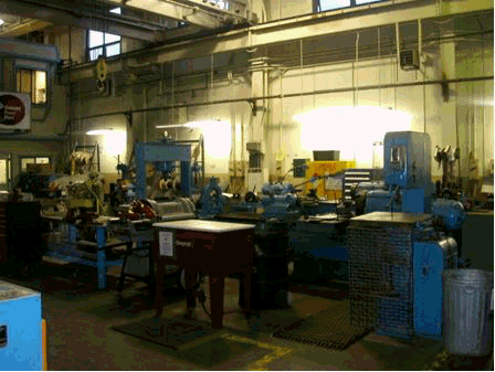
Figure 32 -- The main machine shop.
Equipment included a band saw, cutting tools, a drill press, a grinder, a lathe, and a turn mill. Cutting tools such as drill bits, chucks, milling discs were well-organized and labeled. Precision measuring tools such as micrometers were stored in protective cases and stored in cabinets. General housekeeping appeared to be reasonable. When asked whether the plant has a periodic maintenance program for major tools such as changing oil on a lathe, the Warehouse Manager responded that the plant performs maintenance as necessary.
The electrical shop, to the south of the Administration Building, houses electrical tools such as battery chargers, electric cords, multi-meters, and portable generators. According to the Warehouse Manager, the equipment in this shop is vital for work such as rewinding motors and repairing motor bearings. The shop appeared well-organized and clean.
The secondary machine shop, originally dedicated to Units 6 and 7, now houses miscellaneous tools (Figure 33). Equipment and materials ranged from welding machines to cleaning solvent. Yet another dedicated welding shop stands near retired Units 1 to 5 (Figure 34).
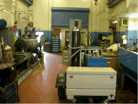
Figure 33 -- The secondary machine shop houses miscellaneous tools.
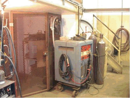
Figure 34 -- A welding machine in the welding shop.
The Auditor asked whether the plant has a periodic maintenance program for welding machines. The Warehouse Manager responded that there are at least six machines onsite, generally more than are needed. If necessary, the plant easily rents another machine nearby. He stated that buying a new welding machine is cheaper than fixing an old, worn machine.
The tool room houses tools that are not available elsewhere. Technicians follow a formal check-out procedure to obtain the necessary tools for their job. The Auditor observed three check-out binders on the front desk of the tool room, one for contractors, one for plant personnel, and the third for the demolition crews working on Units 1 to 5. The binders conformed to the plant's procedure on materials and inventory management, OMP 8-0.
The Production Team Leader stated that plant staff calibrate Instrumentation and Control (I&C) equipment whenever the equipment is deployed on a maintenance task. I&C equipment include deadweight testers (used to calibrate pressure sensors), pneumatic calibrators, and manometers. He said that a time-based calibration program is uneconomical because equipment is not used on a consistent basis. When asked whether there has ever been a situation when an outage or maintenance activity was delayed due to improper calibration of an instrument, the Manager responded that there are multiple levels of redundancy on all I&C equipment. Further, the Manager stated that the plant can always borrow equipment as needed from the nearby Morro Bay Power Plant.
Operation Standard 1 - Safety
The protection of life and limb for the work force is paramount. GAOs have a comprehensive safety program in place at each site. The company behavior ensures that personnel at all levels of the organization consider safety as the overriding priority. This is manifested in decisions and actions based on this priority. The work environment and the policies and procedures foster such a safety culture, and the attitudes and behaviors of personnel are consistent with the policies and procedures.
Assessment Guideline
C. Work practice norms in the organization promote the safety culture in that:
1. Appropriate defenses, such as technical accuracy, precautions, cautions and notes, are explicitly embedded in procedures, processes, and equipment configuration to minimize the occurrences and consequences of inappropriate action.
The Auditor reviewed the following safety documents for compliance with power plant safety regulations and found them in order:
1. Permit to operate a boiler
2. Test and inspection records for boiler safety valves
3. Material Safety Data Sheets (MSDS)
4. Lockout/Tagout procedures
5. Confined space entry procedures
6. Boiler inspection reports
7. Fire protection equipment test reports
8. Emergency Response Plan
The Auditor also observed that the plant followed the above safety procedures.
Boiler safety valves were in locations and had proper tag numbers according to the safety records (P&ID) for those valves. MSDS were in a binder where they were readily visible and accessible to plant personnel in the chemistry laboratory. The Production Team Leader demonstrated that the plant's computer system correctly generates standard forms, tags and system design templates consistent with the plant's lockout and tagout procedures. See Observation 3.17. Access doors to boiler equipment were properly marked as confined spaces.
Operation Standard 14 - Clearances
Work is performed on equipment only when safe. When necessary, equipment is taken out of service, de-energized, controlled, and tagged in accordance with a clearance procedure. Personnel are trained in the clearance procedure and its use, and always verify that equipment is safe before any work proceeds.
Among other things:
A. The GAO prepares and maintains a clearance procedure. The clearance procedure contains requirements for removing a component from service and/or placing a component back into service.
B. The GAO ensures that personnel are trained in and follow the clearance procedure
Assessment Guidelines
A. Clearance tags state clearly what equipment and systems are out of service, who can authorize and remove a clearance, and who can provide more information regarding the reason for issuing the clearance tag.
B. Clearance tags state clearly who requested and approved the clearance, and what must be done to remove the clearance.
C. The clearance procedure clearly describes which personnel are responsible for issuing and removing clearances.
D. Plant logbooks show the operation of all valves, switches and devices required to isolate equipment.
E. Tags are non-reusable, attachable by hand, self-locking, and secure unless deliberate effort is applied.
F. Clearance approvals assure that equipment status will not be changed during the duration of the clearance.
G. Procedures assure that full information is provided when assignments are handed off between personnel or between shifts.
After a circuit breaker fire in July 2003, Moss Landing reviewed its procedures for lockout and tagout of equipment. During a scheduled outage for Unit 6, workers carelessly inserted a circuit breaker into a cabinet. Resulting conductor contact caused an electric arc which in turn caused the fire.
The plant now has an adequate Lockout/Tagout Clearance Procedure. The Auditor reviewed Moss Landing's Lockout/Tagout Procedures, No. 7-11-CA-ML Rev. 2, submitted in accordance with staff's data request. The Auditor spoke with the Production Team Leader about the plant's automated system, which prints hard copies of standard forms, tags and system design templates; all of these items comprise a working tag. The Production Team Leader showed the Auditor the standard forms and tags that were stored in his computer. He said that there are approximately 300 to 400 pre-designed specific system templates used to identify valves and electrical equipment that needs to be isolated, tagged and locked out.
1 The study looked at six performance indices established by the North American Electric Reliability Council (NERC), which included (1) Equivalent forced outage rate during demand (EFORd), (2) Equivalent Availability Factor (EAF), (3) Net Capacity Factor (NCF), (4) Start Reliability (SR), (5) Scheduled Outage Factor (SOF), and (6) Forced Outage Factor (FOF).
2 See ASME B31 Pressure Piping Code
3 The Auditor reviewed three boiler inspection reports for Unit 6:
1. APTECH Engineering Services, dated May 16, 1995, titled Moss Landing Replication of Main Steam Piping Leads and Superheater Outlet Leads,
2. APTECH Engineering Services, dated January 4, 2001, titled Moss Landing Replication of Main Steam Piping Leads and Superheater Outlet Leads,
3. Babcock &Wilcox (B&W), dated July 2005, titled Moss Landing Unit 6 Boiler Inspection Report - Contract No. UP-23
4 For example, see Federal OSHA regulation 1910.165 (b) (2)
5 The Auditor compared the Master Table of Contents, OMP 1-1, dated January 1, 2001, to the Table of Contents for Volume 11.
6 The Auditor reviewed the Welder Qualification Report for T.P. Jones, one of two certified welders onsite.
